Datasheet
3D Model
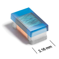
AR376RAA Series
Outgassing Compliant Chip Inductors
AR376RAA Series features exceptionally high Q factors and outstanding self-resonant frequency.
- Standard tin-lead (Sn‑Pb) terminations ensures the best possible board adhesion. Note: Nickel barrier termination (tin-lead over tin over nickel over silver-platinum-glass frit, termination code P) is recommended for hand soldering applications.
- Passes NASA low outgassing specifications
- Exceptionally high Q factors
- Outstanding self-resonant frequency
- Tight inductance tolerance
- High temperature materials allow operation in ambient temperatures up to 155°C.
Specifications
Electrical specifications at 25°C.
Part is not compliant with MIL-STD-981 Family 50, Class S due to wire gauge.
| Part number 1 | Inductance (nH) 2 | Tolerance (%) | Q min 3 | SRF min (MHz) 4 | DCR max (Ω) 5 | Imax (mA) |
|---|---|---|---|---|---|---|
| AR376RAA030JPZ | 3.3 @ 100 MHz | 5 | 29 @ 300 MHz | 5000 | 0.050 | 900 |
| AR376RAA060JPZ | 6.8 @ 100 MHz | 5 | 24 @ 300 MHz | 4380 | 0.070 | 900 |
| AR376RAA100JPZ | 10 @ 100 MHz | 5,2,1 | 31 @ 300 MHz | 3440 | 0.080 | 900 |
| AR376RAA120JPZ | 12 @ 100 MHz | 5,2,1 | 40 @ 300 MHz | 2560 | 0.10 | 900 |
| AR376RAA150JPZ | 15 @ 100 MHz | 5,2,1 | 38 @ 300 MHz | 2520 | 0.10 | 900 |
| AR376RAA180JPZ | 18 @ 100 MHz | 5,2,1 | 50 @ 300 MHz | 2260 | 0.10 | 900 |
| AR376RAA220JPZ | 22 @ 100 MHz | 5,2,1 | 50 @ 300 MHz | 2120 | 0.10 | 900 |
| AR376RAA270JPZ | 27 @ 100 MHz | 5,2,1 | 50 @ 300 MHz | 1800 | 0.11 | 900 |
| AR376RAA330JPZ | 33 @ 100 MHz | 5,2,1 | 55 @ 300 MHz | 1800 | 0.11 | 900 |
| AR376RAA390JPZ | 39 @ 100 MHz | 5,2,1 | 55 @ 300 MHz | 1800 | 0.12 | 900 |
| AR376RAA470JPZ | 47 @ 100 MHz | 5,2,1 | 55 @ 300 MHz | 1500 | 0.13 | 900 |
| AR376RAA560JPZ | 56 @ 100 MHz | 5,2,1 | 55 @ 300 MHz | 1400 | 0.14 | 900 |
| AR376RAA680JPZ | 68 @ 100 MHz | 5,2,1 | 48 @ 150 MHz | 1180 | 0.26 | 600 |
| AR376RAA820JPZ | 82 @ 100 MHz | 5,2,1 | 52 @ 150 MHz | 1120 | 0.21 | 700 |
| AR376RAA101JPZ | 100 @ 100 MHz | 5,2,1 | 55 @ 150 MHz | 1040 | 0.26 | 650 |
| AR376RAA121JPZ | 120 @ 100 MHz | 5,2,1 | 53 @ 150 MHz | 1040 | 0.26 | 620 |
| AR376RAA151JPZ | 150 @ 100 MHz | 5,2,1 | 53 @ 150 MHz | 920 | 0.31 | 720 |
| AR376RAA181JPZ | 180 @ 50.0 MHz | 5,2,1 | 53 @ 150 MHz | 780 | 0.43 | 580 |
| AR376RAA221JPZ | 220 @ 50.0 MHz | 5,2,1 | 51 @ 150 MHz | 700 | 0.50 | 550 |
| AR376RAA271JPZ | 270 @ 50.0 MHz | 5,2,1 | 53 @ 150 MHz | 630 | 0.56 | 470 |
| AR376RAA331JPZ | 330 @ 50.0 MHz | 5,2,1 | 30 @ 35.0 MHz | 570 | 0.62 | 370 |
| AR376RAA391JPZ | 390 @ 50.0 MHz | 5,2,1 | 31 @ 35.0 MHz | 540 | 0.75 | 370 |
| AR376RAA471JPZ | 470 @ 50.0 MHz | 5,2,1 | 31 @ 35.0 MHz | 500 | 1.3 | 320 |
| AR376RAA561JPZ | 560 @ 35.0 MHz | 5,2,1 | 31 @ 35.0 MHz | 440 | 1.3 | 300 |
| AR376RAA621JPZ | 620 @ 35.0 MHz | 5,2,1 | 32 @ 35.0 MHz | 440 | 1.6 | 270 |
| AR376RAA681JPZ | 680 @ 35.0 MHz | 5,2,1 | 32 @ 35.0 MHz | 410 | 1.6 | 260 |
| AR376RAA751JPZ | 750 @ 35.0 MHz | 5,2,1 | 32 @ 35.0 MHz | 400 | 2.2 | 220 |
| AR376RAA821JPZ | 820 @ 35.0 MHz | 5,2,1 | 31 @ 35.0 MHz | 370 | 1.8 | 240 |
| AR376RAA911JPZ | 910 @ 35.0 MHz | 5,2,1 | 31 @ 35.0 MHz | 350 | 2.9 | 190 |
| AR376RAA102JPZ | 1000 @ 35.0 MHz | 5,2,1 | 32 @ 35.0 MHz | 360 | 2.8 | 190 |
| AR376RAA122JPZ | 1200 @ 35.0 MHz | 5,2,1 | 32 @ 35.0 MHz | 320 | 3.2 | 170 |
Notes
- When ordering, please specify tolerance, termination and screening codes: e.g. AR376RAA122JPZ.
- Inductance measured using a Coilcraft SMD-A fixture in an Agilent/ HP 4286A impedance analyzer or equivalent with Coilcraft-provided correlation pieces.
- Q measured using an Agilent/HP 4291A impedance Analyzer with an Agilent/HP 16197A test fixture or equivalents.
- SRF measured using an Agilent/HP 8753ES network analyzer or equivalent and a Coilcraft CCF1297 test fixture.
- DCR measured on a micro-ohmmeter.
Tolerance:
- F = 1%
- G = 2%
- J = 5%
Termination:
For hand soldering applications, the nickel barrier termination (tin-lead over tin over nickel over silver-platinum-glass frit, termination code P) is recommended. Exposed gold or tin in the terminations migrates into the solder.- P = Tin-lead (63/37) over tin over nickel over silver-platinum-glass frit.
- C = Tin-lead (63/37) over gold over nickel over moly-mag.
- S = Tin-lead (63/37) over leach-resistant silver-platinumglass frit.
- A = Gold over nickel over moly-mag.
- L = Silver-palladium-platinum-glass frit.
Screening:
- Z = Unscreened
- Y = Unscreened (SLDC Option A)
- W = Unscreened (SLDC Option B)
- H = Coilcraft CP-SA-10001 Group A
- G = Coilcraft CP-SA-10001 Group A (SLDC Option A)
- D = Coilcraft CP-SA-10001 Group A (SLDC Option B)
- 1 = EEE-INST-002 (Family 3) Level 1
- 2 = EEE-INST-002 (Family 3) Level 2
- 3 = EEE-INST-002 (Family 3) Level 3
- 4 = MIL-STD-981 (Family 50) Class B
- 5 = MIL-STD-981 (Family 50) Class S
- Screening performed to the document’s latest revision.
- Lot qualification (Group B) available.
- Country of origin restrictions available; prefix options G or F.
Environmental
Ambient temperature range:
–55°C to +125°C with Imax current
Storage temperature range:
Component: –55°C to +155°C
Tape and reel packaging: –55°C to +80°C
Tape and reel packaging: –55°C to +80°C
Maximum part temperature:
+155°C (ambient + temp rise)
Failures in Time (FIT) / Mean Time Between Failures (MTBF):
Performance curves
L vs Frequency

Q vs Frequency

Physical characteristics

| A max | B max | C max | D ref | E | F | G | H | I | J | |
|---|---|---|---|---|---|---|---|---|---|---|
| 0.140 | 0.085 | 0.060 | 0.020 | 0.056 | 0.020 | 0.080 | 0.076 | 0.040 | 0.070 | inches |
| 3,56 | 2,16 | 1,52 | 0,51 | 1,42 | 0,51 | 2,03 | 1,93 | 1,02 | 1,78 | mm |
Dimensions are before optional solder application.
For maximum height dimension including solder, add 0.0025 in / 0,64 mm to B and 0.0060 in / 0,15 mm to A and C.
General specification
Core Material:
Ceramic
Weight:
16.5 – 26.5 mg
Packaging:
2000 per 7″ reel Plastic tape: 8 mm wide, 0.3 mm thick, 4 mm pocket spacing, 1.6 mm pocket depth.
Temperature coefficient of inductance:
+25 to +155 ppm/°C
Soldering/Washing
Moisture Sensitivity Level (MSL):
1 (unlimited floor life at <30°C / 85% relative humidity)
Resistance to soldering heat:
Max three 40 second reflows at +260°C, parts cooled to room temperature between cycles.
Refer to Soldering Coilcraft Components before soldering.