Datasheet
3D Model
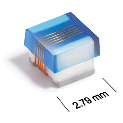
AR413RAD Series
Outgassing Compliant Chip Inductors
This robust version of Coilcraft’s standard 1008HQ series features high temperature materials that pass NASA low outgassing specifications and allow operation in an ambient temperature range of –55°C to 155°C. The standard tin-lead (Sn-Pb) terminations over leach-resistant base metalization ensures the best possible board adhesion.
All parts are compliant with MIL-STD-981 Family 50, Class S.
Looking for the AE/ML/MS versions of this series? They have been replaced by the AR413RAD. Customers who have previously purchased the AE will be supported indefinitely. The ML/MS versions are no longer in production.
All parts are compliant with MIL-STD-981 Family 50, Class S.
Looking for the AE/ML/MS versions of this series? They have been replaced by the AR413RAD. Customers who have previously purchased the AE will be supported indefinitely. The ML/MS versions are no longer in production.
Specifications
Electrical specifications at 25°C.
Part is wound on low profile coilform.
| Part number 1 | Inductance (nH) 2 | Tolerance (%) | Q min 3 | SRF min (GHz) 4 | DCR max (mΩ) 5 | Imax (A) |
|---|---|---|---|---|---|---|
| AR413RAD3N0_PZ | 3.0 | 5 | 57 @ 1000 MHz | 5.00 | 38 | 1.8 |
| AR413RAD4N1_PZ | 4.1 | 5 | 75 @ 1000 MHz | 5.00 | 50 | 1.8 |
| AR413RAD7N8_PZ | 7.8 | 5 | 51 @ 500 MHz | 3.80 | 50 | 1.6 |
| AR413RAD10N_PZ | 10 | 5,2 | 60 @ 500 MHz | 3.20 | 60 | 1.5 |
| AR413RAD12N_PZ | 12 | 5,2 | 57 @ 500 MHz | 2.40 | 60 | 1.5 |
| AR413RAD18N_PZ | 18 | 5,2 | 62 @ 350 MHz | 2.10 | 70 | 1.4 |
| AR413RAD22N_PZ | 22 | 5,2 | 62 @ 350 MHz | 2.05 | 70 | 1.4 |
| AR413RAD33N_PZ | 33 | 5,2 | 49 @ 150 MHz | 1.70 | 90 | 1.2 |
| AR413RAD36N_PZ | 36 | 5,2 | 57 @ 150 MHz | 1.40 | 90 | 1.1 |
| AR413RAD39N_PZ | 39 | 5,2 | 45 @ 150 MHz | 1.30 | 90 | 1.1 |
| AR413RAD47N_PZ | 47 | 5,2,1 | 45 @ 150 MHz | 1.45 | 120 | 0.95 |
| AR413RAD56N_PZ | 56 | 5,2,1 | 43 @ 150 MHz | 1.08 | 120 | 0.95 |
| AR413RAD68N_PZ | 68 | 5,2,1 | 54 @ 150 MHz | 1.15 | 130 | 0.85 |
| AR413RAD82N_PZ | 82 | 5,2,1 | 54 @ 150 MHz | 1.06 | 160 | 0.80 |
| AR413RADR10_PZ | 100 | 5,2,1 | 51 @ 150 MHz | 0.82 | 160 | 0.80 |
Notes
- When ordering, please specify tolerance, termination and screening codes: e.g. AR413RADR10JPZ.
- Inductance measured at 50 MHz using a Coilcraft SMD-A fixture in an Agilent/ HP 4286A impedance analyzer or equivalent with Coilcraft-provided correlation pieces.
- Q measured using an Agilent/HP 4291A with an AgilentHP 16197A test fixture or equivalents.
- SRF measured using an Aglilent/HP 8753ES network analyzeror equivalent and a Coilcraft CCF1502 test fixture.
- DCR measured on a Keithley 580 micro-ohmmeter or equivalent and a Coilcraft CCF858 test fixture.
Tolerance:
- F = 1%
- G = 2%
- J = 5%
Termination:
- P = Tin-lead (63/37) over tin over nickel over silverplatinum-glass frit.
- S = Tin-lead (63/37) over leach-resistant silver-platinumglass frit.
- L = Silver-palladium-platinum-glass frit.
Screening:
- Z = Unscreened
- Y = Unscreened (SLDC Option A)
- W = Unscreened (SLDC Option B)
- H = Coilcraft CP-SA-10001 Group A
- G = Coilcraft CP-SA-10001 Group A (SLDC Option A)
- D = Coilcraft CP-SA-10001 Group A (SLDC Option B)
- 1 = EEE-INST-002 (Family 3) Level 1
- 2 = EEE-INST-002 (Family 3) Level 2
- 3 = EEE-INST-002 (Family 3) Level 3
- 4 = MIL-STD-981 (Family 50) Class B
- 5 = MIL-STD-981 (Family 50) Class S
- F = ESCC3201 (F4 operational life performed at 90°C)
- Screening performed to the document’s latest revision.
- Lot qualification (Group B) available.
- Custom testing also available.
- Country of origin restrictions available; prefix option G or F.
Environmental
Ambient temperature range:
–55°C to +125°C with Imax current
Storage temperature range:
Component: –55°C to +155°C
Tape and reel packaging: –55°C to +80°C
Tape and reel packaging: –55°C to +80°C
Maximum part temperature:
+155°C (ambient + temp rise)
Failures in Time (FIT) / Mean Time Between Failures (MTBF):
Performance curves
Typical L vs Frequency

Typical Q vs Frequency

Physical characteristics

Note: Dimensions are before solder application. For maximum overall dimensions including solder, add 0.0025 in / 0,064 mm to B and 0.006 in / 0,15 mm to A and C.
General specification
Core Material:
Ceramic
Packaging:
2000/7″reel;
Standard height parts: Plastic tape: 8 mm wide, 0.23 mm thick, 4 mm pocket spacing, 1.8 mm pocket depth;
Low profile parts: Plastic tape: 8 mm wide, 0.3 mm thick, 4 mm pocket spacing, 1.6 mm pocket depth.
Standard height parts: Plastic tape: 8 mm wide, 0.23 mm thick, 4 mm pocket spacing, 1.8 mm pocket depth;
Low profile parts: Plastic tape: 8 mm wide, 0.3 mm thick, 4 mm pocket spacing, 1.6 mm pocket depth.
Temperature coefficient of inductance:
+25 to +155 ppm/°C
Soldering/Washing
Moisture Sensitivity Level (MSL):
1 (unlimited floor life at <30°C / 85% relative humidity)
Resistance to soldering heat:
Max three 40 second reflows at +260°C, parts cooled to room temperature between cycles.
Refer to Soldering Coilcraft Components before soldering.