Datasheet
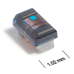
3D Model
CP312RAB Series
Chip Inductors for Critical Applications
CP312RAB Series features ferrite construction for high current handling.
- Higher inductance values than other 0603 inductors.
- Inductance values: 47 nH – 22 µH; 5% and 2% tolerance.
- Silver-palladium-platinum-glass frit terminations.
Specifications
Electrical specifications at 25°C.
| Part number 1 | Inductance (nH) 2 | Tolerance (%) | Q min 3 | SRF min (MHz) 4 | DCR max (Ω) 5 | Imax (mA) | Overall Width |
|---|---|---|---|---|---|---|---|
| CP312RAB47N_LZ | 47 @ 7.9 MHz | 5,2 | 12 @ 7.9 MHz | 1500 | 0.075 | 700 | B1 |
| CP312RAB51N_LZ | 51 @ 7.9 MHz | 5,2 | 12 @ 7.9 MHz | 1400 | 0.075 | 700 | B1 |
| CP312RAB72N_LZ | 72 @ 7.9 MHz | 5,2 | 12 @ 7.9 MHz | 1400 | 0.12 | 700 | B1 |
| CP312RAB101_LZ | 100 @ 7.9 MHz | 5,2 | 12 @ 7.9 MHz | 1150 | 0.13 | 700 | B1 |
| CP312RAB121_LZ | 120 @ 7.9 MHz | 5,2 | 12 @ 7.9 MHz | 1100 | 0.15 | 650 | B1 |
| CP312RAB151_LZ | 150 @ 7.9 MHz | 5,2 | 15 @ 7.9 MHz | 1050 | 0.15 | 660 | B1 |
| CP312RAB181_LZ | 180 @ 7.9 MHz | 5,2 | 15 @ 7.9 MHz | 950 | 0.15 | 660 | B1 |
| CP312RAB241_LZ | 240 @ 7.9 MHz | 5,2 | 15 @ 7.9 MHz | 800 | 0.16 | 620 | B1 |
| CP312RAB271_LZ | 270 @ 7.9 MHz | 5,2 | 15 @ 7.9 MHz | 775 | 0.30 | 420 | B1 |
| CP312RAB331_LZ | 330 @ 7.9 MHz | 5,2 | 15 @ 7.9 MHz | 725 | 0.46 | 350 | B1 |
| CP312RAB391_LZ | 390 @ 7.9 MHz | 5,2 | 15 @ 7.9 MHz | 620 | 0.51 | 350 | B1 |
| CP312RAB471_LZ | 470 @ 7.9 MHz | 5,2 | 15 @ 7.9 MHz | 540 | 0.62 | 310 | B1 |
| CP312RAB561_LZ | 560 @ 7.9 MHz | 5,2 | 15 @ 7.9 MHz | 525 | 0.44 | 390 | B1 |
| CP312RAB681_LZ | 680 @ 7.9 MHz | 5,2 | 15 @ 7.9 MHz | 260 | 0.52 | 330 | B2 |
| CP312RAB781_LZ | 780 @ 7.9 MHz | 5,2 | 15 @ 7.9 MHz | 460 | 0.83 | 260 | B1 |
| CP312RAB821_LZ | 820 @ 7.9 MHz | 5,2 | 15 @ 7.9 MHz | 410 | 0.69 | 280 | B1 |
| CP312RAB102_LZ | 1000 @ 7.9 MHz | 5,2 | 15 @ 7.9 MHz | 190 | 0.81 | 250 | B2 |
| CP312RAB122_LZ | 1200 @ 7.9 MHz | 5,2 | 15 @ 7.9 MHz | 160 | 0.87 | 230 | B2 |
| CP312RAB152_LZ | 1500 @ 7.9 MHz | 5,2 | 15 @ 7.9 MHz | 100 | 0.96 | 230 | B2 |
| CP312RAB182_LZ | 1800 @ 7.9 MHz | 5,2 | 15 @ 7.9 MHz | 80.0 | 1.1 | 210 | B2 |
| CP312RAB222_LZ | 2200 @ 7.9 MHz | 5,2 | 15 @ 7.9 MHz | 68.0 | 1.2 | 210 | B2 |
| CP312RAB272_LZ | 2700 @ 7.9 MHz | 5,2 | 15 @ 7.9 MHz | 60.0 | 1.5 | 170 | B2 |
| CP312RAB332_LZ | 3300 @ 7.9 MHz | 5,2 | 15 @ 7.9 MHz | 42.0 | 1.5 | 185 | B2 |
| CP312RAB392_LZ | 3900 @ 7.9 MHz | 5,2 | 15 @ 7.9 MHz | 40.0 | 1.6 | 185 | B2 |
| CP312RAB472_LZ | 4700 @ 7.9 MHz | 5,2 | 15 @ 7.9 MHz | 34.0 | 2.1 | 170 | B2 |
| CP312RAB562_LZ | 5600 @ 7.9 MHz | 5,2 | 15 @ 7.9 MHz | 32.0 | 2.6 | 150 | B2 |
| CP312RAB682_LZ | 6800 @ 7.9 MHz | 5,2 | 15 @ 7.9 MHz | 31.0 | 3.1 | 120 | B2 |
| CP312RAB782_LZ | 7800 @ 7.9 MHz | 5,2 | 15 @ 7.9 MHz | 28.0 | 3.5 | 120 | B2 |
| CP312RAB822_LZ | 8200 @ 7.9 MHz | 5,2 | 15 @ 7.9 MHz | 26.0 | 3.6 | 120 | B2 |
| CP312RAB103_LZ | 10000 @ 2.5 MHz | 5,2 | 12 @ 2.5 MHz | 25.0 | 4.8 | 100 | B2 |
| CP312RAB153_LZ | 15000 @ 2.5 MHz | 5,2 | 20 @ 2.5 MHz | 23.0 | 7.1 | 90 | B2 |
| CP312RAB183_LZ | 18000 @ 2.5 MHz | 5,2 | 20 @ 2.5 MHz | 22.0 | 7.6 | 85 | B2 |
| CP312RAB223_LZ | 22000 @ 2.5 MHz | 5,2 | 22 @ 2.5 MHz | 19.0 | 8.8 | 70 | B2 |
Notes
- When ordering, please specify tolerance, termination and testing codes: e.g. CP312RAB822JLZ.
- Inductance measured using a Coilcraft SMD-A fixture in an Agilent/HP4286A impedance analyzer or equivalent with Coilcraft-provided correlation pieces.
- Q measured using an Agilent/HP 4291A with an Agilent/HP 16197A test fixture or equivalents.
- SRF measured using an Agilent/HP 8753ES network analyzer or equivalent and a Coilcraft SMD-D test fixture.
- DCR measured on a Keithley 580 micro-ohmmeter or equivalent and a Coilcraft CCF1010 test fixture.
Tolerance:
- G = 2%
- J = 5%
Termination:
- L = Silver-palladium-platinum-glass frit.
- T = Tin-silver-copper (95.5/4/0.5). (Special order, added cost)
- S = Tin-lead (63/37). (Special order, added cost)
Testing:
- Z = Unscreened
- H = Group A screening per Coilcraft CP-SA-10001
Environmental
Ambient temperature range:
–40°C to +85°C with Irms current.
Storage temperature range:
Component: –65°C to +100°C.
Tape and reel packaging: –55°C to +80°C.
Tape and reel packaging: –55°C to +80°C.
Maximum part temperature:
+100°C (ambient + temp rise).
Failures in Time (FIT) / Mean Time Between Failures (MTBF):
Performance curves
L vs Frequency

Q vs Frequency

Physical characteristics

| A max | B | C max | D ref | E | F | G | H | I | J | |
|---|---|---|---|---|---|---|---|---|---|---|
| 0.071 | See note 2 | 0.044 | 0.015 | 0.030 | 0.013 | 0.034 | 0.040 | 0.025 | 0.025 | inches |
| 1,80 | 1,12 | 0,38 | 0,76 | 0,33 | 0,86 | 1,02 | 0,64 | 0,64 | mm |
1. Dimensions are before optional solder application. For maximum overall dimensions including solder, add 0.0025 in / 0,064 mm to B and 0.006 in / 0,15 mm to A and C.
2. B1 = 0.040 ±0.004 in / 1,016 ±0,102 mm
B2 = 0.046 ±0.004 in / 1,169 ±0,102 mm
General specification
Core Material:
Ceramic/Ferrite
Weight:
4.8 – 6.2 mg
Packaging:
2000 per 7′′ reel. Plastic tape: 8 mm wide, 0.23 mm thick, 4 mm pocket spacing, 1.1 mm pocket depth.
Temperature coefficient of inductance:
+50 to +150 ppm/°C.
Soldering/Washing
Moisture Sensitivity Level (MSL):
1 (unlimited floor life at <30°C / 85% relative humidity).
Resistance to soldering heat:
Max three 40 second reflows at +260°C, parts cooled to room temperature between cycles.
Refer to Soldering Coilcraft Components before soldering.