Datasheet
3D Model
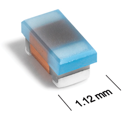
AR312RAA Series
Outgassing Compliant Chip Inductors
Coilcraft AR312RAA Series have exceptional Q and high SRFs. High temperature materials allow operation in ambient temperatures up to 155°C.
- DCR and current carrying characteristics.
- Outstanding self-resonant frequency.
- Tight inductance tolerance.
- Passes NASA low outgassing specifications.
- Standard tin-lead (Sn-Pb) terminations ensures the best possible board adhesion. Note: Nickel barrier termination (tin-lead over tin over nickel over silver-platinum-glass frit, termination code P) is recommended for hand soldering applications.
- Tin-lead (63/37) over tin over nickel over silver-platinumglass frit terminations. Other terminations are also available.
Specifications
Electrical specifications at 25°C.
Part is not compliant with MIL-STD-981 Family 50, Class S due to wire gauge.
| Part number 1 | Inductance (nH) 2 | Tolerance (%) | 900 MHz | 1.7 GHz | Q min 3 | SRF min (MHz) 4 | DCR max (Ω) 5 | Imax (mA) | ||
|---|---|---|---|---|---|---|---|---|---|---|
| L typ | Q typ 3 | L typ | Q typ 3 | |||||||
| AR312RAA1N6JPZ | 1.6 @ 250 MHz | 5 | 1.67 | 49 | 1.65 | 63 | 26 @ 250 MHz | > 5000 | 0.022 | 700 |
| AR312RAA1N8JPZ | 1.8 @ 250 MHz | 5 | 1.83 | 35 | 1.86 | 50 | 21 @ 250 MHz | > 5000 | 0.045 | 700 |
| AR312RAA3N3_PZ | 3.3 @ 250 MHz | 5,2 | 3.31 | 75 | 3.38 | 88 | 35 @ 250 MHz | > 5000 | 0.045 | 700 |
| AR312RAA3N6_PZ | 3.6 @ 250 MHz | 5,2 | 3.72 | 53 | 3.71 | 65 | 18 @ 250 MHz | > 5000 | 0.063 | 700 |
| AR312RAA3N9_PZ | 3.9 @ 250 MHz | 5,2 | 3.95 | 49 | 3.96 | 67 | 20 @ 250 MHz | > 5000 | 0.080 | 700 |
| AR312RAA4N3_PZ | 4.3 @ 250 MHz | 5,2 | 4.32 | 50 | 4.33 | 70 | 29 @ 250 MHz | > 5000 | 0.063 | 700 |
| AR312RAA4N7_PZ | 4.7 @ 250 MHz | 5,2 | 4.72 | 47 | 4.75 | 57 | 18 @ 250 MHz | > 5000 | 0.116 | 605 |
| AR312RAA5N1_PZ | 5.1 @ 250 MHz | 5,2 | 4.93 | 47 | 4.95 | 56 | 20 @ 250 MHz | > 5000 | 0.140 | 510 |
| AR312RAA5N6_PZ | 5.6 @ 250 MHz | 5,2,1 | 5.77 | 63 | 6.05 | 80 | 25 @ 250 MHz | 4760 | 0.075 | 700 |
| AR312RAA6N8_PZ | 6.8 @ 250 MHz | 5,2,1 | 6.75 | 60 | 7.1 | 81 | 28 @ 250 MHz | 4660 | 0.110 | 700 |
| AR312RAA7N5_PZ | 7.5 @ 250 MHz | 5,2,1 | 7.7 | 60 | 7.82 | 65 | 23 @ 250 MHz | 4320 | 0.106 | 700 |
| AR312RAA8N2_PZ | 8.2 @ 250 MHz | 5,2,1 | 8.25 | 82 | 8.37 | 87 | 26 @ 250 MHz | 3880 | 0.115 | 700 |
| AR312RAA8N7_PZ | 8.7 @ 250 MHz | 5,2,1 | 8.86 | 62 | 9.32 | 58 | 27 @ 250 MHz | 3680 | 0.109 | 700 |
| AR312RAA9N5_PZ | 9.5 @ 250 MHz | 5,2,1 | 9.7 | 59 | 9.92 | 61 | 22 @ 250 MHz | 4100 | 0.135 | 700 |
| AR312RAA10N_PZ | 10 @ 250 MHz | 5,2,1 | 10 | 66 | 10.6 | 83 | 28 @ 250 MHz | 3860 | 0.130 | 700 |
| AR312RAA11N_PZ | 11 @ 250 MHz | 5,2,1 | 11 | 53 | 11.5 | 56 | 26 @ 250 MHz | 3640 | 0.130 | 700 |
| AR312RAA12N_PZ | 12 @ 250 MHz | 5,2,1 | 12.3 | 72 | 13.5 | 83 | 29 @ 250 MHz | 3220 | 0.130 | 620 |
| AR312RAA15N_PZ | 15 @ 250 MHz | 5,2,1 | 15.4 | 64 | 16.8 | 89 | 28 @ 250 MHz | 3020 | 0.170 | 600 |
| AR312RAA16N_PZ | 16 @ 250 MHz | 5,2,1 | 16.2 | 55 | 17.3 | 52 | 29 @ 250 MHz | 3040 | 0.170 | 600 |
| AR312RAA18N_PZ | 18 @ 250 MHz | 5,2,1 | 18.7 | 70 | 21.4 | 69 | 29 @ 250 MHz | 2680 | 0.170 | 600 |
| AR312RAA22N_PZ | 22 @ 250 MHz | 5,2,1 | 22.8 | 73 | 26.1 | 71 | 31 @ 250 MHz | 2380 | 0.190 | 560 |
| AR312RAA23N_PZ | 23 @ 250 MHz | 5,2,1 | 24.1 | 71 | 28 | 67 | 39 @ 250 MHz | 2380 | 0.190 | 560 |
| AR312RAA24N_PZ | 24 @ 250 MHz | 5,2,1 | 24.5 | 45 | 28.7 | 39 | 36 @ 250 MHz | 2380 | 0.190 | 560 |
| AR312RAA27N_PZ | 27 @ 250 MHz | 5,2,1 | 29.2 | 74 | 34.6 | 65 | 32 @ 250 MHz | 2380 | 0.220 | 530 |
| AR312RAA30N_PZ | 30 @ 250 MHz | 5,2,1 | 31.4 | 47 | 39.9 | 28 | 32 @ 250 MHz | 2240 | 0.220 | 500 |
| AR312RAA33N_PZ | 33 @ 250 MHz | 5,2,1 | 36 | 67 | 49.5 | 42 | 33 @ 250 MHz | 1900 | 0.220 | 500 |
| AR312RAAR33_PZ | 33 @ 100 MHz | 5,2,1 | - | - | - | - | 25 @ 100 MHz | 620 | 3.890 | 100000 |
| AR312RAA36N_PZ | 36 @ 250 MHz | 5,2,1 | 39.4 | 47 | 52.7 | 24 | 32 @ 250 MHz | 1960 | 0.250 | 460 |
| AR312RAA39N_PZ | 39 @ 250 MHz | 5,2,1 | 42.7 | 60 | 60.2 | 40 | 36 @ 250 MHz | 1740 | 0.250 | 460 |
| AR312RAA43N_PZ | 43 @ 250 MHz | 5,2,1 | 47 | 44 | 64.9 | 21 | 28 @ 250 MHz | 1580 | 0.280 | 440 |
| AR312RAA47N_PZ | 47 @ 200 MHz | 5,2,1 | 52.2 | 62 | 77.2 | 35 | 35 @ 200 MHz | 1560 | 0.280 | 440 |
| AR312RAA51N_PZ | 51 @ 200 MHz | 5,2,1 | 55.5 | 69 | 82.2 | 34 | 38 @ 200 MHz | 1560 | 0.300 | 420 |
| AR312RAA56N_PZ | 56 @ 200 MHz | 5,2,1 | 62.5 | 56 | 97 | 26 | 37 @ 200 MHz | 1480 | 0.310 | 420 |
| AR312RAA68N_PZ | 68 @ 200 MHz | 5,2,1 | 80.5 | 54 | 168 | 21 | 35 @ 200 MHz | 1380 | 0.340 | 410 |
| AR312RAA72N_PZ | 72 @ 150 MHz | 5,2,1 | 82 | 53 | 135 | 20 | 35 @ 150 MHz | 1360 | 0.490 | 340 |
| AR312RAA82N_PZ | 82 @ 150 MHz | 5,2,1 | 96.2 | 54 | 177 | 21 | 29 @ 150 MHz | 1300 | 0.540 | 340 |
| AR312RAAR10_PZ | 100 @ 150 MHz | 5,2,1 | 124 | 49 | - | - | 28 @ 150 MHz | 1140 | 0.580 | 310 |
| AR312RAAR11_PZ | 110 @ 150 MHz | 5,2,1 | 138 | 43 | - | - | 30 @ 150 MHz | 1080 | 0.610 | 310 |
| AR312RAAR12_PZ | 120 @ 150 MHz | 5,2,1 | 166 | 39 | - | - | 28 @ 150 MHz | 1020 | 0.650 | 270 |
| AR312RAAR15_PZ | 150 @ 150 MHz | 5,2,1 | 250 | 25 | - | - | 28 @ 150 MHz | 900 | 0.915 | 250 |
| AR312RAAR18_PZ | 180 @ 100 MHz | 5,2,1 | 305 | 22 | - | - | 25 @ 100 MHz | 820 | 1.250 | 210 |
| AR312RAAR20_PZ | 200 @ 100 MHz | 5,2,1 | - | - | - | - | 25 @ 100 MHz | 800 | 1.980 | 170 |
| AR312RAAR21_PZ | 210 @ 100 MHz | 5,2,1 | - | - | - | - | 27 @ 100 MHz | 780 | 2.060 | 160 |
| AR312RAAR22_PZ | 220 @ 100 MHz | 5,2,1 | - | - | - | - | 25 @ 100 MHz | 760 | 2.100 | 160 |
| AR312RAAR27_PZ | 270 @ 100 MHz | 5,2,1 | - | - | - | - | 26 @ 100 MHz | 700 | 2.300 | 150 |
Notes
- When ordering, please specify tolerance, termination and screening codes: e.g. AR312RAAR27JSZ.
- Inductance measured using a Coilcraft SMD-A test fixture and Coilcraft-provided correlation pieces with an Agilent/HP 4286A impedance analyzer or equivalent.
- Q measured at the same frequency as inductance using an Agilent/HP 4291A with an Agilent/HP 16197A test fixture or equivalents.
- SRF measured using an Agilent/HP 8753ES network analyzer and a Coilcraft CCF1232 test fixture.
- DCR measured on a Keithley 580 micro-ohmmeter and a Coilcraft CCF1010 test fixture.
Tolerance:
- F = 1%
- G = 2%
- J = 5%
Termination:
For hand soldering applications, the nickel barrier termination (tin-lead over tin over nickel over silver-platinum-glass frit, termination code P) is recommended. Exposed gold or tin in the terminations migrates into the solder.- P = Tin-lead (63/37) over tin over nickel over silverplatinum-glass frit.
- C = Tin-lead (63/37) over gold over nickel over moly-mag.
- S = Tin-lead (63/37) over leach-resistant silver-platinumglass frit.
- A = Gold over nickel over moly-mag.
- L = Silver-palladium-platinum-glass frit.
Screening:
- Z = Unscreened
- Y = Unscreened (SLDC Option A)
- W = Unscreened (SLDC Option B)
- H = Coilcraft CP-SA-10001 Group A
- G = Coilcraft CP-SA-10001 Group A (SLDC Option A)
- D = Coilcraft CP-SA-10001 Group A (SLDC Option B)
- 1 = EEE-INST-002 (Family 3) Level 1
- 2 = EEE-INST-002 (Family 3) Level 2
- 3 = EEE-INST-002 (Family 3) Level 3
- 4 = MIL-STD-981 (Family 50) Class B
- 5 = MIL-STD-981 (Family 50) Class S
- F = ESCC3201 (F4 operational life performed at 90°C)
- Screening performed to the document’s latest revision.
- Lot qualification (Group B) available.
- Testing T and U have been replaced with more detailed codes 4, 5, and 1, 2, 3, respectively. Codes T and U can still be used, if necessary. Custom testing also available.
- Country of origin restrictions available; prefix options G or F.
Environmental
Ambient temperature range:
–55°C to +125°C with Imax current.
Storage temperature range:
Component: –55°C to +155°C.
Tape and reel packaging: –55°C to +80°C.
Tape and reel packaging: –55°C to +80°C.
Maximum part temperature:
+155°C (ambient + temp rise).
Failures in Time (FIT) / Mean Time Between Failures (MTBF):
Performance curves
Typical L vs Frequency


General specification
Core Material:
Ceramic
Packaging:
2000 per 7″ reel Paper tape: 8 mm wide, 1.0 mm thick, 4 mm pocket spacing.
Temperature coefficient of inductance:
+25 to +155 ppm/°C.
Soldering/Washing
Moisture Sensitivity Level (MSL):
1 (unlimited floor life at <30°C / 85% relative humidity).
Resistance to soldering heat:
Max three 40 second reflows at +260°C, parts cooled to room temperature between cycles.
Refer to Soldering Coilcraft Components before soldering.