Datasheet
3D Models
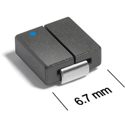
AE515PMM, AE515PMD Series
Outgassing Compliant Power Inductors
AE515PMM and AE515PMD are designed for high-speed switch mode applications.
Can be used as 1:1 transformers or in SEPIC applications
Passes NASA low outgassing specifications
Tin-lead (Sn-Pb) terminations for the best possible board adhesion
Passes NASA low outgassing specifications
Tin-lead (Sn-Pb) terminations for the best possible board adhesion
Specifications
Electrical specifications at 25°C.
Single Conductor
| Part number 1 |
Inductance (µH)
2
(Tolerance: ±20%) |
DCR ± 5% (mΩ) 3 | SRF ref (GHz) 4 | Isat (A) 5 | Irms (A) 6 |
|---|---|---|---|---|---|
| AE515PMM500MSZ | 0.050 | 0.123 | 3.80 | 50 | 40 |
| AE515PMM640MSZ | 0.064 | 0.123 | 3.65 | 32 | 40 |
| AE515PMM820MSZ | 0.082 | 0.123 | 3.75 | 22 | 40 |
| AE515PMM101MSZ | 0.100 | 0.123 | 3.75 | 20 | 40 |
Dual Conductor
| Part number 1 | Leads connected in parallel | Leads connected in series | ||||||||
|---|---|---|---|---|---|---|---|---|---|---|
|
L (µH)
2
(±20%) |
DCR ± 5% (mΩ) 3 | SRF ref (GHz) 4 | Isat (A) 5 | Irms (A) 6 |
L (µH)
2
(±20%) |
DCR max (mΩ) 3 | SRF ref (GHz) 4 | Isat (A) 5 | Irms (A) 6 | |
| AE515PMD500MSZ | 0.050 | 0.209 | 3.75 | 50 | 38 | 0.188 | 1.000 | 1.5 | 21 | 17 |
| AE515PMD640MSZ | 0.064 | 0.209 | 3.65 | 32 | 38 | 0.272 | 1.000 | 1.3 | 14 | 17 |
| AE515PMD820MSZ | 0.082 | 0.209 | 3.75 | 22 | 38 | 0.350 | 1.000 | 1.2 | 11 | 17 |
| AE515PMD101MSZ | 0.100 | 0.209 | 3.75 | 20 | 38 | 0.400 | 1.000 | 0.95 | 8 | 17 |
Notes
- When ordering, specify conductors and screening codes: AE515PMM101MSZ.
- Inductance tested at 100 kHz, 0.1 Vrms using an Agilent/HP 4263B LCR meter or equivalent.
- DCR is measured on a micro-ohmmeter at points indicated in the diagram.

- This information is for design purposes only and shall not be tested during screening.
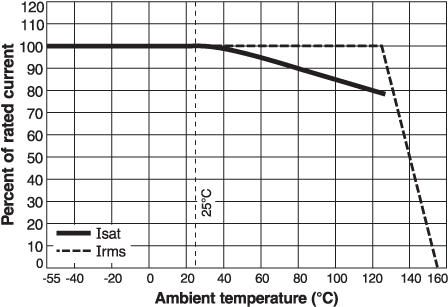
- DC current at 25±C that causes an inductance drops of 20% (typ) from its value without current.
- Current that causes a 40°C rise from 25°C ambient. This information is for reference only and does not represent absolute maximum ratings.
Due to the design of this component, DWV and IR shall not be specified or tested.
Screening:
- Z = Unscreened
- Y = Unscreened (SLDC Option A)
- W = Unscreened (SLDC Option B)
- H = Coilcraft CP-SA-10001 Group A
- G = Coilcraft CP-SA-10001 Group A (SLDC Option A)
- D = Coilcraft CP-SA-10001 Group A (SLDC Option B)
- 1 = EEE-INST-002 (Family 1) Level 1
- 2 = EEE-INST-002 (Family 1) Level 2
- 3 = EEE-INST-002 (Family 1) Level 3
- 4 = MIL-STD-981 (Family 04) Class B
- 5 = MIL-STD-981 (Family 04) Class S
- F = ESCC3201 (F4 operational life performed at 105°C)
- Screening performed to the document’s latest revision.
- Lot qualification (Group B) available.
- Custom testing also available.
Environmental
Ambient temperature range:
–55°C to +125°C with Irms current
Storage temperature range:
Component: –55°C to +155°C
Tape and reel packaging: –40°C to +80°C
Tape and reel packaging: –40°C to +80°C
Maximum part temperature:
+155°C (ambient + temp rise)
Failures in Time (FIT) / Mean Time Between Failures (MTBF):
Performance curves
Typical L vs Current - Dual Conductor

Typical L vs Frequency - Dual Conductor

Typical L vs Current - Single Conductor

Typical L vs Frequency - Single Conductor

Typical Temperature Rise vs Current

Physical characteristics
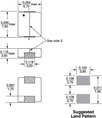
Dimensions - Single Conductor
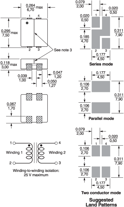
Dimensions - Dual Conductor
Notes:
1. Dimensions are in inches/mm.
2. Dimensions are before optional solder application. For maximum overall dimensions including solder, add 0.0025 in / 0.064 mm to the length, and 0.006 in / 0.15 mm to the height.
3. Top surface is divided by a slot which should be considered when handled by a vacuum pick-and-place process.
General specification
Core Material:
Ferrite
Weight:
0.44 - 0.47 g
Packaging:
500/7′′ reel; Plastic tape: 16 mm wide, 0.33 mm thick, 12 mm pocket spacing, 3.12 mm pocket depth
Soldering/Washing
Moisture Sensitivity Level (MSL):
1 (unlimited floor life at <30°C / 85% relative humidity)
Resistance to soldering heat:
Max three 40 second reflows at +260°C, parts cooled to room temperature between cycles.
Refer to Soldering Coilcraft Components before soldering.