Datasheet
3D Model
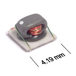
ST458RFW Series
Wideband Transformers for Critical Applications
ST458RFW Series offers 250 mA max current rating.
- Miniature wideband transformer: 4 mm square 3 mm high.
- 300 V interwinding isolation, 1/4 Watt RF input power.
- Tin-silver-copper over silver-platinum-glass frit termination. Other terminations available at additional cost.
Specifications
Electrical specifications at 25°C. Measurements are referenced to 50 Ohms.
| Part number 1 | L min per winding (µH) 2 | DCR max (mΩ) 3 |
Imp. ratio pri:sec 4 |
Current rating (mA) |
Insertion loss (db) |
DC imbalance 5 | Bandwidth (MHz) |
Isolation Voltage (Vrms) |
Schematic | ||
|---|---|---|---|---|---|---|---|---|---|---|---|
| Pri | Sec | Pri | Sec | ||||||||
| ST458RFW01A1LZ | 10 | 10 | 120 | 120 | 1 : 1 | 250 | 0.4 | - | 0.4 — 600 | 300 | A |
| ST458RFW01B1LZ | 9.5 | 9.5 | 75.0 | 75.0 | 1 : 1 | 250 | 0.58 | 36.0 | 0.25 — 750 | 300 | B |
| ST458RFW02B1LZ | 10 | 20 | 120 | 150 | 1 : 2 | 250 | 0.5 | 8.5 | 0.2 — 500 | 300 | B |
| ST458RFW03B1LZ | 9.0 | 27 | 100 | 150 | 1 : 3 | 250 | 0.6 | 8.5 | 0.3 — 900 | 300 | B |
| ST458RFW04B1LZ | 9.0 | 36 | 55.0 | 120 | 1 : 4 | 250 | 1 | 30.0 | 0.25 — 750 | 300 | B |
| ST458RFW04B2LZ | 2.0 | 8.0 | 50.0 | 100 | 1 : 4 | 250 | 2 | 15.0 | 1.5 — 1200 | 300 | B |
| ST458RFW04B3LZ | 5.0 | 20 | 80.0 | 120 | 1 : 4 | 250 | 0.9 | 10.0 | 0.5 — 1000 | 300 | B |
| ST458RFW04B4LZ | 9.0 | 36 | 80.0 | 200 | 1 : 4 | 250 | 0.65 | 7.5 | 0.3 — 700 | 300 | B |
| ST458RFW04C1LZ | 9.0 | 36 | 60.0 | 120 | 1 : 4 | 250 | 1 | 30.0 | 0.25 — 800 | 300 | C |
| ST458RFW08B1LZ | 22 | 176 | 120 | 310 | 1 : 8 | 250 | 0.6 | 17.0 | 0.15 — 600 | 300 | D |
| ST458RFW09B1LZ | 9.0 | 81 | 80.0 | 230 | 1 : 9 | 250 | 0.54 | 5.0 | 0.3 — 500 | 300 | B |
| ST458RFW16B1LZ | 5.0 | 80 | 80.0 | 230 | 1 : 16 | 250 | 0.8 | 5.0 | 0.6 — 300 | 300 | B |
Notes
- When ordering, please specify termination and testing codes: e.g. ST458RFW04C1LZ.
- Inductance measured at 100 kHz, 0.1 V, 0 Adc on an Agilent/HP 4192 or equivalent.
- DCR measured on a micro-ohmmeter.
- Impedance ratio is for the full primary winding to the full secondary winding.
- DC imbalance is the maximum difference in current measured at pins 4 and 6 with the source at pin 5. Inductance drop is 15% at maximum imbalance.
Termination:
- L = Tin-silver-copper (95.5/4/0.5) over silver-platinum-glass frit.
- S = Tin-lead (63/37). (Special order,added cost)
Testing:
Z = UnscreenedH = Group A screening per Coilcraft CP-SA-10001
All screening performed to the document’s latest revision
Custom screening also available
Environmental
Ambient temperature range:
–40°C to +85°C
Storage temperature range:
Component: –55°C to +95°C
Tape and reel packaging: –55°C to +80°C
Tape and reel packaging: –55°C to +80°C
Maximum part temperature:
+95°C (ambient + temp rise)
Failures in Time (FIT) / Mean Time Between Failures (MTBF):
Performance curves
Attenuation vs Frequency


Schematics


General specification
Core Material:
Ferrite
Packaging:
750/7′′ reel; Plastic tape: 12 mm wide, 0.3 mm thick, 8 mm pocket spacing, 2.9 mm pocket depth.
Soldering/Washing
Moisture Sensitivity Level (MSL):
1 (unlimited floor life at <30°C / 85% relative humidity)
Resistance to soldering heat:
Max three 40 second reflows at +260°C, parts cooled to room temperature between cycles.
Refer to Soldering Coilcraft Components before soldering.