Datasheet
3D Model
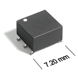
AE520RFA Series
Outgassing Compliant Wideband Transformers
AE520RFA Series offers 250 mA max current rating.
- Small wideband transformer: 7.2 × 6.43 × 4.45 mm high.
- Passes NASA low outgassing specifications.
- 300 V interwinding isolation, 1/4 Watt RF input power.
- Tin-lead terminations for the best possible board adhesion.
- Tin-lead over tin over nickel over phos bronze terminations.
Specifications
Electrical specifications at 25°C.
| Part number 1 | L min per winding (µH) 2 | DCR max (mΩ) 3 |
Imp. ratio pri:sec 4 |
Current rating (mA) |
Insertion loss (db) |
Bandwidth (MHz) |
Isolation Voltage (Vrms) |
Schematic | ||
|---|---|---|---|---|---|---|---|---|---|---|
| Pri | Sec | Pri | Sec | |||||||
| AE520RFA01A1SZ | 60 | 60 | 130 | 130 | 1 : 1 | 250 | 0.25 | 0.045 — 365 | 300 | 1 |
| AE520RFA01B1SZ | 60 | 60 | 130 | 130 | 1 : 1 | 250 | 0.25 | 0.045 — 365 | 300 | 2 |
| AE520RFA02B1SZ | 60 | 140 | 130 | 180 | 1 : 2 | 250 | 0.25 | 0.045 — 495 | 300 | 2 |
| AE520RFA03B1SZ | 40 | 140 | 120 | 180 | 1 : 3 | 250 | 0.35 | 0.075 — 425 | 300 | 2 |
| AE520RFA04B1SZ | 25 | 100 | 90.0 | 160 | 1 : 4 | 250 | 0.6 | 0.12 — 440 | 300 | 2 |
| AE520RFA08B1SZ | 25 | 180 | 90.0 | 180 | 1 : 8 | 250 | 0.6 | 0.105 — 300 | 300 | 2 |
| AE520RFA09B1SZ | 40 | 420 | 120 | 250 | 1 : 9 | 250 | 0.3 | 0.075 — 200 | 300 | 2 |
| AE520RFA16B1SZ | 25 | 420 | 90.0 | 250 | 1 : 16 | 250 | 0.6 | 0.105 — 135 | 300 | 2 |
Notes
- When ordering, please specify screening code: e.g. AE520RFA16B1SZ.
- Inductance measured at 100 kHz, 0.1 V, 0 Adc on an Voltech AT3600 or equivalent.
- DCR measured on a Voltech AT3600 or equivalent.
- Impedance ratio is for the full primary winding to the full secondary winding.
Screening:
Z = UnscreenedH = Group A screening per Coilcraft CP-SA-10001
1 = EEE-INST-002 level 1
2 = EEE-INST-002 level 2
3 = EEE-INST-002 level 3
4 = MIL-STD-981 Class B
5 = MIL-STD-981 Class S
F = Screening per ESCC 3201
All screening performed to the document’s latest revision Custom screening also available
Note: Screening T and U have been replaced with more detailed codes 4, 5, and 1, 2, 3, respectively. Codes T and U can still be used, if necessary.
Environmental
Ambient temperature range:
–55°C to +125°C
Storage temperature range:
Component: –55°C to +125°C
Tape and reel packaging: –55°C to +80°C
Tape and reel packaging: –55°C to +80°C
Maximum part temperature:
+125°C (ambient + temp rise)
Failures in Time (FIT) / Mean Time Between Failures (MTBF):
Performance curves
Attenuation vs Frequency


Schematics


General specification
Core Material:
Ferrite
Weight:
200 – 230 mg
Packaging:
250/7′′reel; Plastic tape: 12 mm wide, 0.3 mm thick, 8 mm pocket spacing,
2.9 mm pocket depth
2.9 mm pocket depth
Soldering/Washing
Moisture Sensitivity Level (MSL):
1 (unlimited floor life at <30°C / 85% relative humidity)
Resistance to soldering heat:
Max three 40 second reflows at +260°C, parts cooled to room temperature between cycles.
Refer to Soldering Coilcraft Components before soldering.