Specifications
Electrical specifications at 25°C.
| Part number 1 |
Inductance min (µH) |
DCR max (Ω) | Turns Ratio |
Volt-time product (V-µs) 3 |
Frequency (kHz) | Sensed current (A) 4 |
Terminating resistance RT (Ω) 5 |
Isolation Voltage (Vrms) |
|
|---|---|---|---|---|---|---|---|---|---|
| pri ref (Ω) | sec max (mΩ) | pri ref : Sec1 | |||||||
| CP-N0530-0602SZ | 730 | 0.0007 | 1980 | 1 : 60 | 32.4 | 15 — 1000 | 10.0 | 6.0 | 500 |
Notes
- When ordering, specify termination and screening codes: e.g. CP-N0530-1252SZ.
- Inductance measured between secondary pins at 100 kHz, 0.1 Vrms.
- Volt-time product is for the secondary, between pin 6 and 4 for CP-N0530-xxx1 and between pin 1 and 3 for CP-N0530-xxx2.
- Primary current of 10 A causes approximately 12°C temperature rise from 25°C ambient. Higher current causes a greater temperature rise (see Temperature Rise vs Current curve).
- Terminating resistance (RT) value is based on 1 Volt output with 10 Amps flowing through the primary. Varying terminating resistance increases or decreases output Voltage/Ampere according to the following equation: RT (Ohms) = Vout × Nsec/Iin.
Termination:
- S = Tin-lead (63/37)
- T = RoHS Tin-silver-copper (95.5/4/0.5)
Screening:
- Z = Unscreened
- H = Coilcraft CP-SA-10001 Group A
- 1 =EEE-INST-002 (Family 1) Level 1
- 2 =EEE-INST-002 (Family 1) Level 2
- 3 =EEE-INST-002 (Family 1) Level 3
- 4 = MIL-STD-981 (Family 03) Class B
- 5 = MIL-STD-981 (Family 03) Class S
- F =ESCC3201 (F4 operational life performed at 105°C)
- Screening performed to the document’s latest revision.
- Lot qualification (Group B) available.
- Testing T and U have been replaced with more detailed codes 4, 5, and 1, 2, 3, respectively. Codes T and U can still be used, if necessary. Custom testing also available.
Environmental
Ambient temperature range:
–55°C to +125°C
Storage temperature range:
Component: –55°C to +155°C.
Tape and reel packaging: –55°C to +80°C
Tape and reel packaging: –55°C to +80°C
Maximum part temperature:
+155°C (ambient + temp rise)
Failures in Time (FIT) / Mean Time Between Failures (MTBF):
Performance curves
Temperature Rise vs Current

Schematics
.PNG "cpn0530_schematics-(1).PNG")
.PNG "cpn0530_pinouts-(1).PNG")
General specification
Core Material:
Ferrite
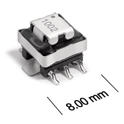
Weight:
0.4 g
Packaging:
250/7′′ reel Plastic tape: 16 mm wide, 0.35 mm thick, 12 mm pocket spacing, 5.6 mm pocket depth
Soldering/Washing
Moisture Sensitivity Level (MSL):
1 (unlimited floor life at <30°C / 85% relative humidity)
Resistance to soldering heat:
Max three 40 second reflows at +260°C, parts cooled to room temperature between cycles
Refer to Soldering Coilcraft Components before soldering.