Datasheet
3D Model
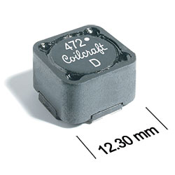
ML612PND Series
High-Reliability Coupled Inductors
The ML612PND series of coupled inductors was designed for high temperature applications – up to 155°C. The excellent coupling coefficient (k ≥ 0.98) makes it ideal for use in SEPIC applications. In SEPIC topologies, the required inductance for each winding in a coupled inductor is half the value needed for two separate inductors, allowing selection of a part with lower DCR and higher current handling.
These inductors provide high inductance, high efficiency, excellent current handling and 500 V isolation in a very rugged part. They are well suited for use as VRM inductors in high-current DC-DC and VRM/VRD controllers.
They can also be used as two single inductors connected in series or parallel, as a common mode choke or as a 1 : 1 transformer.
They can also be used as two single inductors connected in series or parallel, as a common mode choke or as a 1 : 1 transformer.
Specifications
Electrical specifications at 25°C.
For Flyback Applications
| Part number 1 | Inductance (µH) 2 | Tolerance (%) | DCR max (Ω) 3 |
Isolation Voltage (V) 4 |
Leakage Inductance (µH) |
|---|---|---|---|---|---|
| ML612PND472MLZ | 4.7 | 20 | 0.040 | 500 | 0.22 |
| ML612PND562MLZ | 5.6 | 20 | 0.046 | 500 | 0.23 |
| ML612PND682MLZ | 6.8 | 20 | 0.048 | 500 | 0.22 |
| ML612PND822MLZ | 8.2 | 20 | 0.055 | 500 | 0.34 |
| ML612PND103MLZ | 10 | 20 | 0.058 | 500 | 0.34 |
| ML612PND123MLZ | 12 | 20 | 0.062 | 500 | 0.36 |
| ML612PND153MLZ | 15 | 20 | 0.072 | 500 | 0.41 |
| ML612PND183MLZ | 18 | 20 | 0.080 | 500 | 0.37 |
| ML612PND223MLZ | 22 | 20 | 0.096 | 500 | 0.41 |
| ML612PND273MLZ | 27 | 20 | 0.12 | 500 | 0.43 |
| ML612PND333MLZ | 33 | 20 | 0.15 | 500 | 0.56 |
| ML612PND393MLZ | 39 | 20 | 0.16 | 500 | 0.64 |
| ML612PND473MLZ | 47 | 20 | 0.18 | 500 | 0.7 |
| ML612PND563MLZ | 56 | 20 | 0.19 | 500 | 0.76 |
| ML612PND683MLZ | 68 | 20 | 0.21 | 500 | 0.88 |
| ML612PND823MLZ | 82 | 20 | 0.28 | 500 | 0.85 |
| ML612PND104MLZ | 100 | 20 | 0.30 | 500 | 0.9 |
| ML612PND124KLZ | 120 | 10 | 0.41 | 500 | 1.31 |
| ML612PND154KLZ | 150 | 10 | 0.46 | 500 | 1.46 |
| ML612PND184KLZ | 180 | 10 | 0.51 | 500 | 0.93 |
| ML612PND224KLZ | 220 | 10 | 0.69 | 500 | 1.54 |
| ML612PND274KLZ | 270 | 10 | 0.90 | 500 | 1.17 |
| ML612PND334KLZ | 330 | 10 | 1.0 | 500 | 4.14 |
| ML612PND394KLZ | 390 | 10 | 1.1 | 500 | 1.64 |
| ML612PND474KLZ | 470 | 10 | 1.5 | 500 | 1.25 |
| ML612PND564KLZ | 560 | 10 | 1.7 | 500 | 2.68 |
| ML612PND684KLZ | 680 | 10 | 2.3 | 500 | 2.11 |
| ML612PND824KLZ | 820 | 10 | 2.6 | 500 | 2.39 |
| ML612PND105KLZ | 1000 | 10 | 2.9 | 500 | 4.28 |
For SEPIC Applications
| Part number 1 | Inductance (µH) 2 | Tolerance (%) | DCR max (Ω) 3 | SRF (MHz) 5 | Coupling coefficient |
Leakage Inductance (µH) |
Isat (A) 6 | Irms (A) | ||||
|---|---|---|---|---|---|---|---|---|---|---|---|---|
| Min | Typ | 10% drop | 20% drop | 30% drop | both windings 7 | one winding 8 | ||||||
| ML612PND472MLZ | 4.7 | 20 | 0.040 | 26.0 | 33.0 | 0.98 | 0.22 | 13.9 | 15.2 | 16.4 | 3.16 | 4.47 |
| ML612PND562MLZ | 5.6 | 20 | 0.046 | 24.0 | 30.0 | 0.98 | 0.23 | 13.4 | 14.9 | 15.7 | 2.87 | 4.06 |
| ML612PND682MLZ | 6.8 | 20 | 0.048 | 18.0 | 23.0 | 0.98 | 0.22 | 12.1 | 13.6 | 14.2 | 2.81 | 3.98 |
| ML612PND822MLZ | 8.2 | 20 | 0.055 | 16.0 | 20.0 | 0.98 | 0.34 | 10.3 | 11.5 | 12.2 | 2.76 | 3.90 |
| ML612PND103MLZ | 10 | 20 | 0.058 | 14.0 | 17.0 | 0.98 | 0.34 | 8.8 | 10.0 | 10.7 | 2.56 | 3.62 |
| ML612PND123MLZ | 12 | 20 | 0.062 | 12.0 | 15.0 | 0.98 | 0.36 | 8.2 | 9.2 | 9.7 | 2.48 | 3.50 |
| ML612PND153MLZ | 15 | 20 | 0.072 | 10.0 | 13.0 | 0.99 | 0.41 | 7.4 | 8.4 | 9.0 | 2.30 | 3.25 |
| ML612PND183MLZ | 18 | 20 | 0.080 | 9.6 | 12.0 | 0.99 | 0.37 | 6.5 | 7.4 | 7.9 | 2.18 | 3.08 |
| ML612PND223MLZ | 22 | 20 | 0.096 | 8.8 | 11.0 | 0.99 | 0.41 | 6.0 | 6.8 | 7.3 | 1.99 | 2.81 |
| ML612PND273MLZ | 27 | 20 | 0.12 | 8.0 | 10.0 | 0.99 | 0.43 | 5.8 | 6.6 | 7.0 | 1.78 | 2.52 |
| ML612PND333MLZ | 33 | 20 | 0.15 | 7.6 | 9.5 | 0.99 | 0.56 | 5.5 | 6.1 | 6.5 | 1.59 | 2.25 |
| ML612PND393MLZ | 39 | 20 | 0.16 | 6.8 | 8.5 | 0.99 | 0.64 | 4.7 | 5.3 | 5.6 | 1.54 | 2.18 |
| ML612PND473MLZ | 47 | 20 | 0.18 | 6.0 | 7.5 | 0.99 | 0.70 | 3.7 | 4.3 | 4.6 | 1.45 | 2.05 |
| ML612PND563MLZ | 56 | 20 | 0.19 | 5.6 | 7.0 | 0.99 | 0.76 | 3.6 | 4.2 | 4.5 | 1.41 | 2.00 |
| ML612PND683MLZ | 68 | 20 | 0.21 | 5.2 | 6.5 | 0.99 | 0.88 | 3.5 | 4.0 | 4.3 | 1.35 | 1.90 |
| ML612PND823MLZ | 82 | 20 | 0.28 | 4.0 | 5.0 | 0.99 | 0.85 | 3.3 | 3.7 | 4.0 | 1.16 | 1.65 |
| ML612PND104MLZ | 100 | 20 | 0.30 | 3.6 | 4.5 | >0.99 | 0.90 | 2.8 | 3.2 | 3.5 | 1.13 | 1.59 |
| ML612PND124KLZ | 120 | 10 | 0.41 | 3.4 | 4.3 | 0.99 | 1.3 | 2.6 | 2.9 | 3.2 | 0.96 | 1.36 |
| ML612PND154KLZ | 150 | 10 | 0.46 | 3.3 | 4.1 | >0.99 | 1.5 | 2.2 | 2.5 | 2.7 | 0.91 | 1.29 |
| ML612PND184KLZ | 180 | 10 | 0.51 | 3.2 | 4.0 | >0.99 | 0.93 | 2.1 | 2.4 | 2.6 | 0.86 | 1.22 |
| ML612PND224KLZ | 220 | 10 | 0.69 | 2.7 | 3.4 | >0.99 | 1.5 | 1.9 | 2.2 | 2.3 | 0.74 | 1.05 |
| ML612PND274KLZ | 270 | 10 | 0.90 | 2.5 | 3.1 | >0.99 | 1.2 | 1.7 | 1.9 | 2.1 | 0.65 | 0.92 |
| ML612PND334KLZ | 330 | 10 | 1.0 | 2.3 | 2.9 | 0.99 | 4.1 | 1.5 | 1.7 | 1.8 | 0.61 | 0.86 |
| ML612PND394KLZ | 390 | 10 | 1.1 | 2.2 | 2.7 | >0.99 | 1.6 | 1.4 | 1.6 | 1.7 | 0.58 | 0.82 |
| ML612PND474KLZ | 470 | 10 | 1.5 | 1.8 | 2.2 | >0.99 | 1.3 | 1.3 | 1.5 | 1.6 | 0.50 | 0.70 |
| ML612PND564KLZ | 560 | 10 | 1.7 | 1.6 | 2.0 | >0.99 | 2.7 | 1.2 | 1.3 | 1.5 | 0.47 | 0.67 |
| ML612PND684KLZ | 680 | 10 | 2.3 | 1.4 | 1.7 | >0.99 | 2.1 | 1.0 | 1.1 | 1.2 | 0.41 | 0.58 |
| ML612PND824KLZ | 820 | 10 | 2.6 | 1.1 | 1.4 | >0.99 | 2.4 | 0.90 | 1.0 | 1.2 | 0.39 | 0.55 |
| ML612PND105KLZ | 1000 | 10 | 2.9 | 1.0 | 1.3 | >0.99 | 4.3 | 0.85 | 0.95 | 1.1 | 0.37 | 0.52 |
Notes
- When ordering, please specify screening code: e.g. ML612PND105KLZ.
- Inductance shown for each winding, measured at 100 kHz, 0.1 Vrms, 0 Adc on an Agilent/HP 4284A LCR meter or equivalent. When leads are connected in parallel, inductance is the same value. When leads are connected in series, inductance is four times the value.
- DCR is for each winding. When leads are connected in parallel, DCR is half the value. When leads are connected in series, DCR is twice the value.
- Winding-to-winding and winding-to-core isolation 500 Vrms.
- SRF measured using an Agilent/HP 4191A or equivalent. When leads are connected in parallel, SRF is the same value.
- DC current, at which the inductance drops the specified amount from its value without current. It is the sum of the current flowing in both windings.
- Equal current when applied to each winding simultaneously that causes a 40°C temperature rise from 25°C ambient.
- Maximum current when applied to one winding that causes a 40°C temperature rise from 25°C ambient.
Refer to Doc 639 “Selecting Coupled Inductors for SEPIC Applications.”
Screening:
- Z = Unscreened
- Y = Unscreened (SLDC Option A)
- W = Unscreened (SLDC Option B)
- H = Group A screening per Coilcraft CP-SA-10001
- G= Coilcraft CP-SA-10001 Group A (SLDC Option A)
- D = Coilcraft CP-SA-10001 Group A (SLDC Option B)
- Screening performed to the document’s latest revision.
- Custom screening also available.
- Country of origin restrictions available; prefix option G.
Environmental
Ambient temperature range:
–55°C to +105°C with Irms current.
Storage temperature range:
Component: –55C to +155°C.
Tape and reel packaging: –55°C to +80°C.
Tape and reel packaging: –55°C to +80°C.
Maximum part temperature:
+155°C (ambient + temp rise).
Failures in Time (FIT) / Mean Time Between Failures (MTBF):
Performance curves
L vs Frequency

L vs Current

Schematics


General specification
Core Material:
Ferrite
Weight:
3.8 g – 4.6 g
Packaging:
500/13″ reel; Plastic tape: 24 mm wide, 0.4 mm thick, 16 mm pocket spacing, 8.1 mm pocket depth
Soldering/Washing
Moisture Sensitivity Level (MSL):
1 (unlimited floor life at <30°C / 85% relative humidity).
Resistance to soldering heat:
Max three 40 second reflows at +260°C, parts cooled to room temperature between cycles.
Refer to Soldering Coilcraft Components before soldering.