Datasheet
3D Model
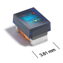
MS450RAB Series
High-Reliability Chip Inductors
Robust version of Coilcraft’s standard 1812LS series features high temperature materials that allow operation in ambient temperatures up to 155°C.
The leach-resistant base metalization with tin-lead (Sn-Pb) terminations ensures the best possible board adhesion.
Specifications
Electrical specifications at 25°C.
| Part number |
Inductance (µH)
1
(Tolerance: ±5%) |
Q typ 2 | SRF min (MHz) 3 | DCR max (Ω) 4 | Imax (mA) |
|---|---|---|---|---|---|
| MS450RAB123JSZ | 12 @ 2.5 MHz | 22 @ 790 kHz | 55.0 | 2.0 | 280 |
| MS450RAB153JSZ | 15 @ 2.5 MHz | 22 @ 790 kHz | 45.0 | 2.5 | 260 |
| MS450RAB183JSZ | 18 @ 2.5 MHz | 24 @ 790 kHz | 37.0 | 2.8 | 240 |
| MS450RAB223JSZ | 22 @ 2.5 MHz | 20 @ 790 kHz | 32.0 | 3.2 | 210 |
| MS450RAB273JSZ | 27 @ 2.5 MHz | 24 @ 790 kHz | 27.0 | 3.6 | 200 |
| MS450RAB333JSZ | 33 @ 2.5 MHz | 22 @ 790 kHz | 23.0 | 4.0 | 190 |
| MS450RAB393JSZ | 39 @ 2.5 MHz | 20 @ 790 kHz | 19.0 | 4.5 | 185 |
| MS450RAB473JSZ | 47 @ 2.5 MHz | 24 @ 790 kHz | 16.0 | 5.0 | 180 |
| MS450RAB563JSZ | 56 @ 2.5 MHz | 22 @ 790 kHz | 13.0 | 5.5 | 170 |
| MS450RAB683JSZ | 68 @ 2.5 MHz | 24 @ 790 kHz | 10.0 | 6.0 | 150 |
| MS450RAB823JSZ | 82 @ 2.5 MHz | 24 @ 790 kHz | 9.0 | 7.0 | 135 |
| MS450RAB104JSZ | 100 @ 2.5 MHz | 24 @ 790 kHz | 8.5 | 8.0 | 135 |
| MS450RAB124JSZ | 120 @ 790 kHz | 25 @ 790 kHz | 8.5 | 11.5 | 110 |
| MS450RAB154JSZ | 150 @ 790 kHz | 23 @ 790 kHz | 8.5 | 13.0 | 100 |
| MS450RAB184JSZ | 180 @ 790 kHz | 24 @ 790 kHz | 8.0 | 14.2 | 85 |
| MS450RAB224JSZ | 220 @ 790 kHz | 23 @ 790 kHz | 6.0 | 16.2 | 80 |
| MS450RAB274JSZ | 270 @ 790 kHz | 23 @ 790 kHz | 5.0 | 20.5 | 75 |
| MS450RAB334JSZ | 330 @ 790 kHz | 24 @ 790 kHz | 4.5 | 22.5 | 70 |
| MS450RAB394JSZ | 390 @ 790 kHz | 14 @ 250 kHz | 3.5 | 24.5 | 65 |
| MS450RAB474JSZ | 470 @ 790 kHz | 15 @ 250 kHz | 3.0 | 26.5 | 65 |
| MS450RAB564JSZ | 560 @ 790 kHz | 13 @ 250 kHz | 2.0 | 28.5 | 65 |
| MS450RAB684JSZ | 680 @ 790 kHz | 13 @ 250 kHz | 1.9 | 38.5 | 60 |
| MS450RAB824JSZ | 820 @ 790 kHz | 13 @ 250 kHz | 1.6 | 41.0 | 50 |
| MS450RAB105JSZ | 1000 @ 790 kHz | 15 @ 250 kHz | 1.5 | 44.0 | 50 |
Notes
- Inductance at 2.5 MHz measured using an Agilent/HP 4286A and a Coilcraft SMD-A fixture with Coilcraft-provided correlation pieces. Inductance at 0.79 MHz measured using an Agilent/HP 4192A and Coilcraft SMD-B test fixture.
- Q read at test frequency directly on an Agilent/HP 4192A LF impedance analyzer and a Coilcraft SMD-B test fixture.
- SRF measured using an Agilent/HP 8753D network analyzer and a Coilcraft SMD-D test fixture.
- DCR measured on a Cambridge Technology micro-ohmmeter.
Environmental
Ambient temperature range:
–55°C to +125°C with Imax current.
Storage temperature range:
Component: –55°C to +155°C.
Tape and reel packaging: –55°C to +80°C.
Tape and reel packaging: –55°C to +80°C.
Maximum part temperature:
+155°C (ambient + temp rise).
Failures in Time (FIT) / Mean Time Between Failures (MTBF):
Performance curves
L vs Frequency

Q vs Frequency

Physical characteristics

| A max | B max | C max | D ref | E | F | G | H | I | J | |
|---|---|---|---|---|---|---|---|---|---|---|
| 0.195 | 0.150 | 0.135 | 0.070 | 0.100 | 0.025 | 0.128 | 0.120 | 0.045 | 0.118 | inches |
| 4,95 | 3,81 | 3,43 | 1,78 | 2,54 | 0,64 | 3,25 | 3,05 | 1,14 | 3,00 | mm |
General specification
Core Material:
Ferrite
Packaging:
600 per 7′′ reel Plastic tape: 12 mm wide, 0.3 mm thick, 8 mm pocket spacing, 3.7 mm pocket depth
Temperature coefficient of inductance:
+200 to +700 ppm/°C.
Soldering/Washing
Moisture Sensitivity Level (MSL):
1 (unlimited floor life at <30°C / 85% relative humidity).
Resistance to soldering heat:
Max three 40 second reflows at +260°C, parts cooled to room temperature between cycles.
Refer to Soldering Coilcraft Components before soldering.