Datasheet
3D Model
Specifications
Electrical specifications at 25°C.
| Part number |
Inductance (µH)
1
(Tolerance: ±10%) |
Q typ
@ 2.5 MHz 2 |
SRF min (MHz) 3 | Isat (A) 4 | DCR max (Ω) 5 | Imax (A) |
|---|---|---|---|---|---|---|
| MS413RAM112KSZ | 1.1 | 24 | 376 | 1.3 | 0.130 | 0.72 |
Notes
- Inductance measured at 2.5 MHz using Coilcraft SMD-A fixture in an Agilent/HP 4286A impedance analyzer or equivalent with Coilcraft-provided correlation pieces.
- Q measured at 2.5 MHz using an Agilent/HP 4291A with an Agilent/HP 16197 test fixture or equivalents.
- SRF measured using an Agilent/HP 8753ES network analyzer or equivalent with a Coilcraft SMD-D fixture.
- DC current at 25°C that causes a 10% (typ) inductance drop from its value without current.
- DCR measured on a Keithley 580 micro-ohmmeter or equivalent and a Coilcraft CCF858 test fixture.
Environmental
Ambient temperature range:
–55°C to +125°C with Imax current.
Storage temperature range:
Component: –55°C to +155°C.
Tape and reel packaging: –55°C to +80°C.
Tape and reel packaging: –55°C to +80°C.
Maximum part temperature:
+155°C (ambient + temp rise).
Failures in Time (FIT) / Mean Time Between Failures (MTBF):
Performance curves
L vs Frequency

Q vs Frequency

L vs Current

Physical characteristics

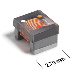
Dimensions are in inches⁄mm
Terminal dimensions are without optional solder applied. For dimensions with optional solder, add 0.006 inches / 0,152 mm.
Visit Color Codes for RF Inductors for an explanation of the color dots.
General specification
Core Material:
Ferrite
Packaging:
2000 per 7′′ reel Plastic tape: 8 mm wide, 0.3 mm thick, 4 mm pocket spacing, 2.0 mm pocket depth.
Temperature coefficient of inductance:
+100 to +350 ppm/°C.
Soldering/Washing
Moisture Sensitivity Level (MSL):
1 (unlimited floor life at <30°C / 85% relative humidity).
Resistance to soldering heat:
Max three 40 second reflows at +260°C, parts cooled to room temperature between cycles.
Refer to Soldering Coilcraft Components before soldering.