Datasheet
3D Model
Specifications
Electrical specifications at 25°C.
| Part number 1 |
Inductance (µH)
2
(Tolerance: ±5%) |
Q min
@ 2.5 MHz 3 |
SRF typ (MHz) 4 | DCR max (mΩ) 5 | Imax (mA) |
|---|---|---|---|---|---|
| AR413RAB182JPZ | 1.8 | 20 | 170 | 840 | 370 |
Notes
- When ordering, please specify termination and screening codes: e.g. AR413RAB104JSZ.
- Inductance measured using a Coilcraft SMD-A fixture in an Agilent/ HP 4286A impedance analyzer or equivalent with Coilcraft-provided correlation pieces.
- Q measured using an Agilent/HP 4291A with an Agilent/HP 16197 test fixture or equivalents.
- SRF measured using an Agilent/HP 8753ES network analyzer or equivalent with a Coilcraft CCF1502 fixture
- DCR measured on a Keithley 580 micro-ohmmeter or equivalent and a Coilcraft CCF1502 test fixture.
Termination:
- P = Tin-lead (63/37) over tin over nickel over silverplatinum-glass frit.
- S = Tin-lead (63/37) over leach-resistant silverplatinum-glass frit.
- L = Silver-palladium-platinum-glass frit
Screening:
- Z = Unscreened
- Y = Unscreened (SLDC Option A)
- W = Unscreened (SLDC Option B)
- H = Coilcraft CP-SA-10001 Group A
- G = Coilcraft CP-SA-10001 Group A (SLDC Option A)
- D = Coilcraft CP-SA-10001 Group A (SLDC Option B)
- 1 = EEE-INST-002 (Family 3) Level 1
- 2 = EEE-INST-002 (Family 3) Level 2
- 3 = EEE-INST-002 (Family 3) Level 3
- 4 = MIL-STD-981 (Family 50) Class B
- 5 = MIL-STD-981 (Family 50) Class S
- F = ESCC3201 (F4 operational life performed at 90°C)
- Screening performed to the document’s latest revision.
- Lot qualification (Group B) available.
- Custom testing also available.
- Country of origin restrictions available; prefix option G or F.
Environmental
Ambient temperature range:
–55°C to +125°C with Imax current
Storage temperature range:
Component: –55°C to +155°C
Tape and reel packaging: –55°C to +80°C
Tape and reel packaging: –55°C to +80°C
Maximum part temperature:
+155°C (ambient + temp rise)
Failures in Time (FIT) / Mean Time Between Failures (MTBF):
Performance curves
Typical L vs Frequency

Typical Q vs Frequency

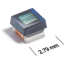
Physical characteristics

Note: Dimensions are before solder application. For maximum overall dimensions including solder, add 0.0025 in / 0,064 mm to B and 0.006 in / 0,15 mm to A and C.
General specification
Core Material:
Ceramic/Ferrite
Weight:
35.0 – 51.0 mg
Packaging:
2000/7″ reel; Plastic tape: 8 mm wide, 0.3 mm thick, 4 mm pocket spacing, 2.0 mm pocket depth
Temperature coefficient of inductance:
+25 to +125 ppm/°C
Soldering/Washing
Moisture Sensitivity Level (MSL):
1 (unlimited floor life at <30°C / 85% relative humidity)
Resistance to soldering heat:
Max three 40 second reflows at +260°C, parts cooled to room temperature between cycles.
Refer to Soldering Coilcraft Components before soldering.