Datasheet
3D Model
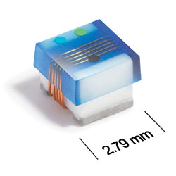
ST413RAD Series
Chip Inductors for Critical Applications
ST413RAD Series features exceptional SRFs, tight tolerance and batch consistency.
- Highest Q factors for this body size, roughly 20% higher than our xx413RAA parts.
- Silver-palladium-platinum-glass frit terminations.
Specifications
Electrical specifications at 25°C.
Part is wound on low profile coilform.
| Part number 1 | Inductance (nH) 2 | Tolerance (%) | Q min 3 | SRF min (GHz) 4 | DCR max (mΩ) 5 | Imax (mA) |
|---|---|---|---|---|---|---|
| ST413RAD3N0_LZ | 3.0 | 5 | 57 @ 1000 MHz | > 5.00 | 38 | 1800 |
| ST413RAD4N1_LZ | 4.1 | 5 | 75 @ 1000 MHz | > 5.00 | 50 | 1800 |
| ST413RAD7N8_LZ | 7.8 | 5 | 51 @ 500 MHz | 3.80 | 50 | 1600 |
| ST413RAD10N_LZ | 10 | 5,2 | 60 @ 500 MHz | 3.20 | 60 | 1500 |
| ST413RAD12N_LZ | 12 | 5,2 | 57 @ 500 MHz | 2.40 | 60 | 1500 |
| ST413RAD18N_LZ | 18 | 5,2 | 62 @ 350 MHz | 2.10 | 70 | 1400 |
| ST413RAD22N_LZ | 22 | 5,2 | 62 @ 350 MHz | 2.05 | 70 | 1400 |
| ST413RAD33N_LZ | 33 | 5,2 | 49 @ 150 MHz | 1.70 | 90 | 1200 |
| ST413RAD36N_LZ | 36 | 5,2 | 57 @ 150 MHz | 1.40 | 90 | 1100 |
| ST413RAD39N_LZ | 39 | 5,2 | 45 @ 150 MHz | 1.30 | 90 | 1100 |
| ST413RAD47N_LZ | 47 | 5,2,1 | 45 @ 150 MHz | 1.45 | 120 | 950 |
| ST413RAD56N_LZ | 56 | 5,2,1 | 43 @ 150 MHz | 1.08 | 120 | 950 |
| ST413RAD68N_LZ | 68 | 5,2,1 | 54 @ 150 MHz | 1.15 | 130 | 850 |
| ST413RAD82N_LZ | 82 | 5,2,1 | 54 @ 150 MHz | 1.06 | 160 | 800 |
| ST413RADR10_LZ | 100 | 5,2,1 | 51 @ 150 MHz | 0.82 | 160 | 800 |
Notes
- When ordering, specify tolerance, termination and testing codes: e.g. ST413RADR10GLZ.
- Inductance measured at 50 MHz using a Coilcraft SMD-A fixture in an Agilent/HP 4286A impedance analyzer or equivalent with Coilcraft-provided correlation pieces.
- Q measured using an Agilent/HP 4291A with an AgilentHP 16197A test fixture or equivalents.
- SRF measured using an Aglilent/HP 8753ES network analyzeror equivalent and a Coilcraft SMD-D test fixture.
- DCR measured on a Keithley 580 micro-ohmmeter or equivalent and a Coilcraft CCF858 test fixture.
Tolerance:
- F = 1%
- G = 2%
- J = 5%
Termination:
- L = Silver-palladium-platinum glass frit.
- S = Tin-lead (63/37) over silver-platinum-glass frit. (Special order, added cost)
- T = Tin-silver-copper (95.5/4/0.5) over silver-platinumglass frit. (Special order, added cost)
Testing:
- Z = Unscreened
- Y = Unscreened (SLDC Option A)
- W = Unscreened (SLDC Option B)
- H = Coilcraft CP-SA-10001 Group A
- G = Coilcraft CP-SA-10001 Group A (SLDC Option A)
- D = Coilcraft CP-SA-10001 Group A (SLDC Option B)
- All screening performed to the document’s latest revision.
- Custom screening also available.
Environmental
Ambient temperature range:
–40°C to +125°C with Imax current
Storage temperature range:
Component: –55°C to +140°C
Tape and reel packaging: –55°C to +80°C
Tape and reel packaging: –55°C to +80°C
Maximum part temperature:
+140°C (ambient + temp rise)
Failures in Time (FIT) / Mean Time Between Failures (MTBF):
Performance curves
L vs Frequency

Q vs Frequency


General specification
Core Material:
Ceramic
Packaging:
2000/7″reel
Standard height parts: Plastic tape: 8 mm wide, 0.23 mm thick, 4 mm pocket spacing, 1.8 mm pocket depth.
Low profile parts: Plastic tape: 8 mm wide, 0.3 mm thick, 4 mm pocket spacing, 1.6 mm pocket depth.
Standard height parts: Plastic tape: 8 mm wide, 0.23 mm thick, 4 mm pocket spacing, 1.8 mm pocket depth.
Low profile parts: Plastic tape: 8 mm wide, 0.3 mm thick, 4 mm pocket spacing, 1.6 mm pocket depth.
Temperature coefficient of inductance:
+25 to +155 ppm/°C
Soldering/Washing
Moisture Sensitivity Level (MSL):
1 (unlimited floor life at <30°C / 85% relative humidity)
Resistance to soldering heat:
Max three 40 second reflows at +260°C, parts cooled to room temperature between cycles.
Refer to Soldering Coilcraft Components before soldering.