Datasheet
3D Model
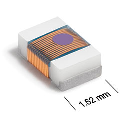
ST336RAF Series
Chip Inductors for Critical Applications
ST336RAF Series wire wound ceramic design provides exceptional Q and high SRF values.
- Lowest profile 0805 surface mount inductors – 0.035′′ high.
- Tight tolerances – many at 2%, some at 1%.
- Matte tin over nickel over silver-platinum glass frit terminations. Other terminations available at additional cost.
Specifications
Electrical specifications at 25°C.
| Part number 1 | Inductance (nH) 2 | Tolerance (%) | Q min 3 | SRF min (MHz) 4 | DCR max (Ω) 5 | Imax (mA) | Color code |
|---|---|---|---|---|---|---|---|
| ST336RAF1N8JRZ | 1.8 @ 250 MHz | 5 | 53 @ 1500 MHz | > 5000 | 0.030 | 800 | Black |
| ST336RAF2N0JRZ | 2.0 @ 250 MHz | 5 | 48 @ 1500 MHz | > 5000 | 0.018 | 800 | Violet |
| ST336RAF3N9JRZ | 3.9 @ 250 MHz | 5 | 54 @ 1000 MHz | > 5000 | 0.055 | 800 | Brown |
| ST336RAF4N3JRZ | 4.3 @ 250 MHz | 5 | 59 @ 1000 MHz | > 5000 | 0.030 | 800 | White |
| ST336RAF4N7JRZ | 4.7 @ 250 MHz | 5 | 63 @ 1000 MHz | 4400 | 0.072 | 800 | Red |
| ST336RAF5N1JRZ | 5.1 @ 250 MHz | 5 | 52 @ 1000 MHz | > 5000 | 0.069 | 800 | Blue |
| ST336RAF5N6JRZ | 5.6 @ 250 MHz | 5 | 49 @ 1000 MHz | 4700 | 0.091 | 800 | Gray |
| ST336RAF6N8JRZ | 6.8 @ 250 MHz | 5 | 64 @ 1000 MHz | 3900 | 0.082 | 800 | Orange |
| ST336RAF7N5JRZ | 7.5 @ 250 MHz | 5 | 47 @ 1000 MHz | 3700 | 0.082 | 800 | Black |
| ST336RAF8N2JRZ | 8.2 @ 250 MHz | 5 | 56 @ 1000 MHz | 3900 | 0.082 | 800 | Yellow |
| ST336RAF9N1JRZ | 9.1 @ 250 MHz | 5 | 58 @ 1000 MHz | 3200 | 0.105 | 780 | Red |
| ST336RAF10N_RZ | 10 @ 250 MHz | 5,2 | 68 @ 750 MHz | 2700 | 0.082 | 800 | Green |
| ST336RAF12N_RZ | 12 @ 250 MHz | 5,2 | 59 @ 750 MHz | 3100 | 0.100 | 790 | Blue |
| ST336RAF15N_RZ | 15 @ 250 MHz | 5,2 | 57 @ 500 MHz | 2400 | 0.100 | 740 | Violet |
| ST336RAF18N_RZ | 18 @ 250 MHz | 5,2 | 58 @ 500 MHz | 2500 | 0.130 | 740 | Gray |
| ST336RAF20N_RZ | 20 @ 250 MHz | 5,2 | 50 @ 500 MHz | 2200 | 0.170 | 680 | Yellow |
| ST336RAF22N_RZ | 22 @ 250 MHz | 5,2 | 52 @ 500 MHz | 2400 | 0.150 | 720 | White |
| ST336RAF27N_RZ | 27 @ 250 MHz | 5,2 | 56 @ 500 MHz | 2000 | 0.190 | 600 | Black |
| ST336RAF33N_RZ | 33 @ 250 MHz | 5,2 | 56 @ 500 MHz | 1900 | 0.190 | 600 | Brown |
| ST336RAF39N_RZ | 39 @ 250 MHz | 5,2,1 | 60 @ 500 MHz | 1800 | 0.270 | 550 | Red |
| ST336RAF47N_RZ | 47 @ 200 MHz | 5,2,1 | 56 @ 500 MHz | 1600 | 0.300 | 550 | Orange |
| ST336RAF56N_RZ | 56 @ 200 MHz | 5,2,1 | 58 @ 500 MHz | 1500 | 0.400 | 470 | Yellow |
| ST336RAF68N_RZ | 68 @ 200 MHz | 5,2,1 | 60 @ 500 MHz | 1200 | 0.400 | 470 | Green |
| ST336RAF82N_RZ | 82 @ 150 MHz | 5,2,1 | 60 @ 500 MHz | 1200 | 0.480 | 430 | Blue |
| ST336RAFR10_RZ | 100 @ 150 MHz | 5,2 | 52 @ 500 MHz | 1000 | 0.640 | 400 | Violet |
| ST336RAFR12_RZ | 120 @ 150 MHz | 5,2 | 46 @ 250 MHz | 950 | 0.680 | 300 | Gray |
| ST336RAFR15_RZ | 150 @ 150 MHz | 5,2 | 44 @ 250 MHz | 850 | 0.800 | 300 | White |
| ST336RAFR18_RZ | 180 @ 150 MHz | 5,2 | 40 @ 250 MHz | 700 | 0.860 | 200 | Black |
| ST336RAFR22_RZ | 220 @ 150 MHz | 5,2 | 34 @ 150 MHz | 700 | 1.290 | 200 | Orange |
| ST336RAFR27_RZ | 270 @ 150 MHz | 5,2 | 34 @ 150 MHz | 650 | 1.400 | 200 | Yellow |
| ST336RAFR33_RZ | 330 @ 150 MHz | 5,2 | 35 @ 150 MHz | 600 | 1.930 | 200 | Green |
| ST336RAFR39_RZ | 390 @ 100 MHz | 5,2 | 35 @ 150 MHz | 550 | 2.800 | 170 | Blue |
| ST336RAFR47_RZ | 470 @ 100 MHz | 5,2 | 32 @ 150 MHz | 500 | 3.100 | 160 | Violet |
| ST336RAFR50_RZ | 500 @ 50 MHz | 5,2 | 22 @ 50 MHz | 470 | 3.200 | 150 | Gray |
Notes
- When ordering, please specify tolerance, termination and screening codes: e.g. ST336RAFR50GLZ.
- Inductance measured using a Coilcraft SMD-A fixture in an Agilent/HP 4286A impedance analyzer with Coilcraft-provided correlation pieces.
- Q measured using an Agilent/HP 4291A with an Agilent/HP 16193 test fixture.
- SRF measured using an Agilent/HP 8753D network analyzer and a Coilcraft CCF1297 test fixture.
- DCR measured on a Cambridge Technology micro-ohmmeter and a Coilcraft CCF858 test fixture.
Tolerance:
- F = 1%
- G = 2%
- J = 5%
Termination:
- R = Matte tin over nickel over silver-platinum glass frit.
- L = Silver-palladium-platinum glass frit.
- P = Tin-lead (63/37) over tin over nickel over silver-platinum-glass frit.
- Q = Tin-silver-copper (95.5/4/0.5) over tin over nickel over silver-platinum-glass frit.
- S = Tin-lead (63/37) over silver-platinum-glass frit.
- T = Tin-silver-copper (95.5/4/0.5) over silver-platinum glass frit.
Screening:
- Z = Unscreened
- Y = Unscreened (SLDC Option A)
- W = Unscreened (SLDC Option B)
- H = Coilcraft CP-SA-10001 Group A
- G = Coilcraft CP-SA-10001 Group A (SLDC Option A)
- D = Coilcraft CP-SA-10001 Group A (SLDC Option B)
- Screening performed to the document’s latest revision.
- Lot qualification (Group B) available.
- Custom testing also available.
- Country of origin restrictions available; prefix options G or F.
Environmental
Ambient temperature range:
–40°C to +125°C with Imax current.
Storage temperature range:
Component: –55°C to +140°C.
Tape and reel packaging: –55°C to +80°C.
Tape and reel packaging: –55°C to +80°C.
Maximum part temperature:
+140°C (ambient + temp rise).
Failures in Time (FIT) / Mean Time Between Failures (MTBF):
Performance curves
Typical Q vs Frequency

Typical L vs Frequency


General specification
Core Material:
Ceramic
Packaging:
2000 per 7′′ reel Plastic tape: 8 mm wide, 0.23 mm thick, 4 mm pocket spacing, 0.9 mm pocket depth.
Temperature coefficient of inductance:
+25 to +155 ppm/°C.
Soldering/Washing
Moisture Sensitivity Level (MSL):
1 (unlimited floor life at <30°C / 85% relative humidity).
Resistance to soldering heat:
Max three 40 second reflows at +260°C, parts cooled to room temperature between cycles.
Refer to Soldering Coilcraft Components before soldering.