Datasheet
3D Model
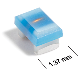
AR319RAD Series
Chip Inductors for Critical Applications
AR319RAD Series combines the exceptionally high Q of an air core inductor with the rugged construction of a ceramic body component.
- Combines the exceptionally high Q of an air core inductor with the rugged construction of a ceramic body component.
- Inductance values: 1.15 nH – 10.4 nH
- Provides intermediate inductance values not available in Coilcraft’s 0603, 0402 or 0906 product families
- High temperature materials allow operation in ambient temperatures up to 155°C.
- Passes NASA low outgassing specifications
- Standard tin-lead (Sn‑Pb) terminations ensures the best possible board adhesion. Note: Nickel barrier termination (tin-lead over tin over nickel over silver-platinum-glass frit, termination code P) is recommended for hand soldering applications.
Specifications
Electrical specifications at 25°C.
| Part number 1 |
Inductance (nH)
2
(Tolerance: ± 5%) |
900 MHz | 1.7 GHz |
Q min
@ 500 MHz 3 |
SRF min (GHz) 4 | DCR max (Ω) 5 | Imax (A) | ||
|---|---|---|---|---|---|---|---|---|---|
| L typ | Q typ 3 | L typ | Q typ 3 | ||||||
| AR319RAD1N1JLZ | 1.15 | 1.2 | 40 | 1.2 | 136 | 25 | 5.0 | 0.021 | 3.0 |
| AR319RAD2N6JLZ | 2.6 | 2.6 | 78 | 2.6 | 163 | 45 | 5.0 | 0.026 | 2.0 |
| AR319RAD4N5JLZ | 4.5 | 4.5 | 103 | 4.7 | 155 | 50 | 5.0 | 0.032 | 1.8 |
| AR319RAD5N0JLZ | 5.0 | 4.9 | 106 | 5.2 | 178 | 60 | 5.0 | 0.032 | 1.6 |
| AR319RAD6N8JLZ | 6.8 | 6.9 | 101 | 7.4 | 172 | 60 | 4.7 | 0.035 | 1.8 |
| AR319RAD7N6JLZ | 7.6 | 7.4 | 109 | 7.9 | 137 | 60 | 4.4 | 0.035 | 1.5 |
| AR319RAD10NJLZ | 10.4 | 10.6 | 103 | 11.5 | 160 | 60 | 4.1 | 0.037 | 1.5 |
Notes
- When ordering, please specify termination and testing codes: e.g. AR319RAD10NJPZ.
- Inductance is measured at 500 MHz on an Agilent 4286A (or equivalent) with a Coilcraft SMD-A test fixture using the listed correlation.
- Q is measured at 500 MHz on an Agilent 4291A (or equivalent) with an Agilent 16197A (or equivalent) test fixture.
- SRF measured using an Agilent/HP 8753ES network analyzer and a Coilcraft CCF1236 test fixture.
- DCR is measured on a Keithley 580 Micro-ohmmeter (or equivalent) with a Coilcraft CCF1010 test fixture.
Termination:
- P = Tin-lead (63/37) over tin over nickel over silver-platinum-glass frit.
- L = Silver-palladium-platinum glass frit. (Special Order, added cost)
- S = Tin-lead (63/37) over silver-palladium-platinum-glass frit. (Special Order, added cost)
Screening:
- Z = Unscreened
- Y = Unscreened (SLDC Option A)
- W = Unscreened (SLDC Option B)
- H = Coilcraft CP-SA-10001 Group A
- G = Coilcraft CP-SA-10001 Group A (SLDC Option A)
- D = Coilcraft CP-SA-10001 Group A (SLDC Option B)
- 1 = EEE-INST-002 (Family 3) Level 1
- 2 = EEE-INST-002 (Family 3) Level 2
- 3 = EEE-INST-002 (Family 3) Level 3
- 4 = MIL-STD-981 (Family 50) Class B
- 5 = MIL-STD-981 (Family 50) Class S
- F = ESCC3201 (F4 operational life performed at 90°C)
- Screening performed to the document’s latest revision.
- Lot qualification (Group B) available.
- Custom testing also available.
- Country of origin restrictions available; prefix option G.
Environmental
Ambient temperature range:
–55°C to +125°C with Imax current.
Storage temperature range:
Component: –55°C to +155°C.
Tape and reel packaging: –55°C to +80°C.
Tape and reel packaging: –55°C to +80°C.
Maximum part temperature:
+155°C (ambient + temp rise).
Failures in Time (FIT) / Mean Time Between Failures (MTBF):
Performance curves
L vs Frequency

Q vs Frequency


General specification
Core Material:
Ceramic
Weight:
4.6 – 5.8 mg
Packaging:
2000 per 7′′ reel; Plastic tape: 8 mm wide, 0.23 mm thick, 4 mm pocket spacing, 1.27 mm pocket depth.
Temperature coefficient of inductance:
+25 to +155 ppm/°C.
Soldering/Washing
Moisture Sensitivity Level (MSL):
1 (unlimited floor life at <30°C / 85% relative humidity).
Resistance to soldering heat:
Max three 40 second reflows at +260°C, parts cooled to room temperature between cycles.
Refer to Soldering Coilcraft Components before soldering.