Datasheet
3D Model
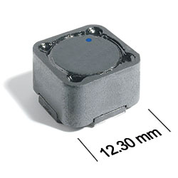
AE612PND Series
Outgassing Compliant Coupled Inductors
The AE612PND series of shielded coupled inductors was designed with special materials that pass NASA low outgassing specifications and allow use in high temperature applications – up to 155°C. Tin-lead (Sn-Pb) terminations are used for the best possible board adhesion.
They offer excellent coupling coefficient (k ≥ 0.98) and can be used in SEPIC applications. In SEPIC topologies, the required inductance for each winding is half the value needed for two separate inductors, allowing selection of a part with lower DCR and higher current handling.
These inductors provide high inductance, high efficiency, excellent current handling and 500 V isolation in a very rugged part. They are well suited for use as VRM inductors in high-current DC-DC and VRM/VRD controllers.
They can also be used as two single inductors connected in series or parallel, as a common mode choke or as a 1 : 1 transformer.
Specifications
Electrical specifications at 25°C.
For Flyback Applications
| Part number 1 | Inductance (µH) 2 | Tolerance (%) | DCR max (Ω) 3 |
Isolation Voltage (V) 4 |
Leakage Inductance (µH) |
|---|---|---|---|---|---|
| AE612PND472MSZ | 4.7 | 20 | 0.040 | 500 | 0.22 |
| AE612PND562MSZ | 5.6 | 20 | 0.046 | 500 | 0.23 |
| AE612PND682MSZ | 6.8 | 20 | 0.048 | 500 | 0.22 |
| AE612PND822MSZ | 8.2 | 20 | 0.055 | 500 | 0.34 |
| AE612PND103MSZ | 10 | 20 | 0.058 | 500 | 0.34 |
| AE612PND123MSZ | 12 | 20 | 0.062 | 500 | 0.36 |
| AE612PND153MSZ | 15 | 20 | 0.072 | 500 | 0.41 |
| AE612PND183MSZ | 18 | 20 | 0.080 | 500 | 0.37 |
| AE612PND223MSZ | 22 | 20 | 0.096 | 500 | 0.41 |
| AE612PND273MSZ | 27 | 20 | 0.12 | 500 | 0.43 |
| AE612PND333MSZ | 33 | 20 | 0.15 | 500 | 0.56 |
| AE612PND393MSZ | 39 | 20 | 0.16 | 500 | 0.64 |
| AE612PND473MSZ | 47 | 20 | 0.18 | 500 | 0.7 |
| AE612PND563MSZ | 56 | 20 | 0.19 | 500 | 0.76 |
| AE612PND683MSZ | 68 | 20 | 0.21 | 500 | 0.88 |
| AE612PND823MSZ | 82 | 20 | 0.28 | 500 | 0.85 |
| AE612PND104MSZ | 100 | 20 | 0.30 | 500 | 0.9 |
| AE612PND124KSZ | 120 | 10 | 0.41 | 500 | 1.31 |
| AE612PND154KSZ | 150 | 10 | 0.46 | 500 | 1.46 |
| AE612PND184KSZ | 180 | 10 | 0.51 | 500 | 0.93 |
| AE612PND224KSZ | 220 | 10 | 0.69 | 500 | 1.54 |
| AE612PND274KSZ | 270 | 10 | 0.90 | 500 | 1.17 |
| AE612PND334KSZ | 330 | 10 | 1.0 | 500 | 4.14 |
| AE612PND394KSZ | 390 | 10 | 1.1 | 500 | 1.64 |
| AE612PND474KSZ | 470 | 10 | 1.5 | 500 | 1.25 |
| AE612PND564KSZ | 560 | 10 | 1.7 | 500 | 2.68 |
| AE612PND684KSZ | 680 | 10 | 2.3 | 500 | 2.11 |
| AE612PND824KSZ | 820 | 10 | 2.6 | 500 | 2.39 |
| AE612PND105KSZ | 1000 | 10 | 2.9 | 500 | 4.28 |
For SEPIC Applications
| Part number 1 | Inductance (µH) 2 | Tolerance (%) | DCR max (Ω) 3 | SRF (MHz) 5 | Coupling coefficient |
Leakage Inductance (µH) |
Isat (A) 6 | Irms (A) | ||||
|---|---|---|---|---|---|---|---|---|---|---|---|---|
| Min | Typ | 10% drop | 20% drop | 30% drop | both windings 7 | one winding 8 | ||||||
| AE612PND472MSZ | 4.7 | 20 | 0.040 | 26.0 | 33.0 | 0.98 | 0.22 | 13.9 | 15.2 | 16.4 | 3.16 | 4.47 |
| AE612PND562MSZ | 5.6 | 20 | 0.046 | 24.0 | 30.0 | 0.98 | 0.23 | 13.4 | 14.9 | 15.7 | 2.87 | 4.06 |
| AE612PND682MSZ | 6.8 | 20 | 0.048 | 18.0 | 23.0 | 0.98 | 0.22 | 12.1 | 13.6 | 14.2 | 2.81 | 3.98 |
| AE612PND822MSZ | 8.2 | 20 | 0.055 | 16.0 | 20.0 | 0.98 | 0.34 | 10.3 | 11.5 | 12.2 | 2.76 | 3.90 |
| AE612PND103MSZ | 10 | 20 | 0.058 | 14.0 | 17.0 | 0.98 | 0.34 | 8.8 | 10.0 | 10.7 | 2.56 | 3.62 |
| AE612PND123MSZ | 12 | 20 | 0.062 | 12.0 | 15.0 | 0.98 | 0.36 | 8.2 | 9.2 | 9.7 | 2.48 | 3.50 |
| AE612PND153MSZ | 15 | 20 | 0.072 | 10.0 | 13.0 | 0.99 | 0.41 | 7.4 | 8.4 | 9.0 | 2.30 | 3.25 |
| AE612PND183MSZ | 18 | 20 | 0.080 | 9.6 | 12.0 | 0.99 | 0.37 | 6.5 | 7.4 | 7.9 | 2.18 | 3.08 |
| AE612PND223MSZ | 22 | 20 | 0.096 | 8.8 | 11.0 | 0.99 | 0.41 | 6.0 | 6.8 | 7.3 | 1.99 | 2.81 |
| AE612PND273MSZ | 27 | 20 | 0.12 | 8.0 | 10.0 | 0.99 | 0.43 | 5.8 | 6.6 | 7.0 | 1.78 | 2.52 |
| AE612PND333MSZ | 33 | 20 | 0.15 | 7.6 | 9.5 | 0.99 | 0.56 | 5.5 | 6.1 | 6.5 | 1.59 | 2.25 |
| AE612PND393MSZ | 39 | 20 | 0.16 | 6.8 | 8.5 | 0.99 | 0.64 | 4.7 | 5.3 | 5.6 | 1.54 | 2.18 |
| AE612PND473MSZ | 47 | 20 | 0.18 | 6.0 | 7.5 | 0.99 | 0.70 | 3.7 | 4.3 | 4.6 | 1.45 | 2.05 |
| AE612PND563MSZ | 56 | 20 | 0.19 | 5.6 | 7.0 | 0.99 | 0.76 | 3.6 | 4.2 | 4.5 | 1.41 | 2.00 |
| AE612PND683MSZ | 68 | 20 | 0.21 | 5.2 | 6.5 | 0.99 | 0.88 | 3.5 | 4.0 | 4.3 | 1.35 | 1.90 |
| AE612PND823MSZ | 82 | 20 | 0.28 | 4.0 | 5.0 | 0.99 | 0.85 | 3.3 | 3.7 | 4.0 | 1.16 | 1.65 |
| AE612PND104MSZ | 100 | 20 | 0.30 | 3.6 | 4.5 | >0.99 | 0.90 | 2.8 | 3.2 | 3.5 | 1.13 | 1.59 |
| AE612PND124KSZ | 120 | 10 | 0.41 | 3.4 | 4.3 | 0.99 | 1.3 | 2.6 | 2.9 | 3.2 | 0.96 | 1.36 |
| AE612PND154KSZ | 150 | 10 | 0.46 | 3.3 | 4.1 | >0.99 | 1.5 | 2.2 | 2.5 | 2.7 | 0.91 | 1.29 |
| AE612PND184KSZ | 180 | 10 | 0.51 | 3.2 | 4.0 | >0.99 | 0.93 | 2.1 | 2.4 | 2.6 | 0.86 | 1.22 |
| AE612PND224KSZ | 220 | 10 | 0.69 | 2.7 | 3.4 | >0.99 | 1.5 | 1.9 | 2.2 | 2.3 | 0.74 | 1.05 |
| AE612PND274KSZ | 270 | 10 | 0.90 | 2.5 | 3.1 | >0.99 | 1.2 | 1.7 | 1.9 | 2.1 | 0.65 | 0.92 |
| AE612PND334KSZ | 330 | 10 | 1.0 | 2.3 | 2.9 | 0.99 | 4.1 | 1.5 | 1.7 | 1.8 | 0.61 | 0.86 |
| AE612PND394KSZ | 390 | 10 | 1.1 | 2.2 | 2.7 | >0.99 | 1.6 | 1.4 | 1.6 | 1.7 | 0.58 | 0.82 |
| AE612PND474KSZ | 470 | 10 | 1.5 | 1.8 | 2.2 | >0.99 | 1.3 | 1.3 | 1.5 | 1.6 | 0.50 | 0.70 |
| AE612PND564KSZ | 560 | 10 | 1.7 | 1.6 | 2.0 | >0.99 | 2.7 | 1.2 | 1.3 | 1.5 | 0.47 | 0.67 |
| AE612PND684KSZ | 680 | 10 | 2.3 | 1.4 | 1.7 | >0.99 | 2.1 | 1.0 | 1.1 | 1.2 | 0.41 | 0.58 |
| AE612PND824KSZ | 820 | 10 | 2.6 | 1.1 | 1.4 | >0.99 | 2.4 | 0.90 | 1.0 | 1.2 | 0.39 | 0.55 |
| AE612PND105KSZ | 1000 | 10 | 2.9 | 1.0 | 1.3 | >0.99 | 4.3 | 0.85 | 0.95 | 1.1 | 0.37 | 0.52 |
Notes
- When ordering, please specify screening code: e.g. AE612PND105KSZ
- Inductance shown for each winding, measured at 100 kHz, 0.1 Vrms, 0 Adc on an Agilent/HP 4284A LCR meter or equivalent. When leads are connected in parallel, inductance is the same value. When leads are connected in series, inductance is four times the value.
- DCR is for each winding. When leads are connected in parallel, DCR is half the value. When leads are connected in series, DCR is twice the value.
- Winding-to-winding and winding-to-core isolation 500 Vrms.
- SRF measured using an Agilent/HP 4191A or equivalent. When leads are connected in parallel, SRF is the same value.
- DC current at 25°C that causes the specified inductance drop from its value without current. It is the sum of the current flowing in both windings.
- Equal current when applied to each winding simultaneously that causes a 40°C temperature rise from 25°C ambient. This information is for reference only and does not represent absolute maximum ratings.
- Maximum current when applied to one winding that causes a 40°C temperature rise from 25°C ambient. This information is for reference only and does not represent absolute maximum ratings.
Refer to Doc 639 “Selecting Coupled Inductors for SEPIC Applications.”
Screening:
- Z = Unscreened
- Y = Unscreened (SLDC Option A)
- W = Unscreened (SLDC Option B)
- H = Coilcraft CP-SA-10001 Group A
- G = Coilcraft CP-SA-10001 Group A (SLDC Option A)
- D = Coilcraft CP-SA-10001 Group A (SLDC Option B)
- 1 = EEE-INST-002 (Family 1) Level 1
- 2 = EEE-INST-002 (Family 1) Level 2
- 3 = EEE-INST-002 (Family 1) Level 3
- 4 = MIL-STD-981 (Family 04) Class B
- 5 = MIL-STD-981 (Family 04) Class S
- F = ESCC3201 (F4 operational life performed at 105°C)
- Screening performed to the document’s latest revision.
- Lot qualification (Group B) available.
- Testing T and U have been replaced with more detailed codes 4, 5, and 1, 2, 3, respectively. Codes T and U can still be used, if necessary. Custom testing also available.
- Country of origin restrictions available; prefix options G or F.
Environmental
Ambient temperature range:
–55°C to +105°C with Irms current.
Storage temperature range:
Component: –55C to +155°C.
Packaging: –55°C to +80°C.
Packaging: –55°C to +80°C.
Maximum part temperature:
+155°C (ambient + temp rise).
Failures in Time (FIT) / Mean Time Between Failures (MTBF):
Performance curves
L vs Frequency

L vs Current

Schematics
.PNG "AE612PND-SCHEM-(1).PNG")

General specification
Core Material:
Ferrite
Weight:
3.8 g – 4.6 g
Packaging:
500/13″ reel; Plastic tape: 24 mm wide, 0.4 mm thick, 16 mm pocket spacing, 8.1 mm pocket depth.
Soldering/Washing
Moisture Sensitivity Level (MSL):
1 (unlimited floor life at <30°C / 85% relative humidity).
Resistance to soldering heat:
Max three 40 second reflows at +260°C, parts cooled to room temperature between cycles.
Refer to Soldering Coilcraft Components before soldering.