Datasheet
3D Model
MS512PJD Series
Coupled Inductors for Critical Applications
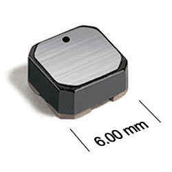
MS512PJD Series coupled inductors for critical applications offer a low profile, only 3.5 mm high and 6 mm square. High inductance, high efficiency and excellent current handling.
- Tight coupling (k ≥ 0.97) makes the MS512PJD series of coupled inductors ideal for use in flyback, multi-output buck and SEPIC applications.
- Tin-lead (Sn-Pb) termination offers the best possible board adhesion.
- Can also be used as two single inductors connected in series or parallel or as a common mode choke.
- Tin-lead (63/37) over tin over nickel terminations.
Specifications
Electrical specifications at 25°C.
For Flyback Applications
| Part number 1 |
Inductance (µH)
2
(Tolerance: ±20%) |
DCR max (Ω) 3 |
Isolation Voltage (V) |
Leakage Inductance (µH) 5 |
|---|---|---|---|---|
| MS512PJD682MSZ | 6.8 | 0.12 | 100 | 0.10 |
| MS512PJD103MSZ | 10 | 0.16 | 100 | 0.12 |
| MS512PJD223MSZ | 22 | 0.30 | 100 | 0.15 |
| MS512PJD473MSZ | 47 | 0.62 | 100 | 0.21 |
| MS512PJD104MSZ | 100 | 1.2 | 100 | 0.45 |
| MS512PJD474MSZ | 470 | 3.5 | 100 | 0.61 |
| MS512PJD105MSZ | 1000 | 7.0 | 100 | 1.1 |
| MS512PJD155MSZ | 1500 | 10.8 | 100 | 1.7 |
| MS512PJD205MSZ | 2000 | 16.0 | 100 | 2.1 |
For SEPIC Applications
| Part number 1 |
Inductance (µH)
2
(Tolerance: ±20%) |
DCR max (Ω) 3 | SRF Typ (MHz) 4 | Coupling coefficient |
Leakage Inductance (µH) 5 |
Isat (A) | Irms (A) | |||
|---|---|---|---|---|---|---|---|---|---|---|
| 10% drop | 20% drop | 30% drop | both windings 6 | one winding 7 | ||||||
| MS512PJD682MSZ | 6.8 | 0.12 | 31.0 | 0.99 | 0.10 | 2.80 | 3.00 | 3.12 | 1.40 | 1.98 |
| MS512PJD103MSZ | 10 | 0.16 | 26.0 | 0.99 | 0.12 | 2.50 | 2.70 | 2.80 | 1.30 | 1.83 |
| MS512PJD223MSZ | 22 | 0.30 | 15.0 | >0.99 | 0.15 | 1.50 | 1.67 | 1.73 | 0.85 | 1.20 |
| MS512PJD473MSZ | 47 | 0.62 | 9.7 | >0.99 | 0.21 | 0.90 | 0.98 | 0.99 | 0.60 | 0.85 |
| MS512PJD104MSZ | 100 | 1.2 | 7.0 | >0.99 | 0.45 | 0.46 | 0.50 | 0.51 | 0.40 | 0.57 |
| MS512PJD474MSZ | 470 | 3.5 | 3.0 | >0.99 | 0.61 | 0.18 | 0.22 | 0.23 | 0.25 | 0.35 |
| MS512PJD105MSZ | 1000 | 7.0 | 1.9 | >0.99 | 1.1 | 0.12 | 0.14 | 0.15 | 0.15 | 0.21 |
| MS512PJD155MSZ | 1500 | 10.8 | 1.5 | >0.99 | 1.7 | 0.10 | 0.12 | 0.13 | 0.14 | 0.20 |
| MS512PJD205MSZ | 2000 | 16.0 | 1.3 | >0.99 | 2.1 | 0.08 | 0.11 | 0.12 | 0.11 | 0.16 |
Notes
- When ordering, please specify termination and screening codes: e.g. MS512PJD105MSZ.
- Inductance shown for each winding, measured at 100 kHz, 0.1 Vrms, 0 Adc on an Agilent/HP 4284A LCR meter or equivalent. When leads are connected in parallel, inductance is the same value. When leads are connected in series, inductance is four times the value.
- DCR is for each winding. When leads are connected in parallel, DCR is half the value. When leads are connected in series, DCR is twice the value.
- SRF measured using an Agilent/HP 4191A or equivalent. When leads are connected in parallel, SRF is the same value.
- Leakage inductance is for L1 and is measured with L2 shorted.
- Equal current when applied to each winding simultaneously that causes a 40°C temperature rise from 25°C ambient. Calculate temperature rise.
- Maximum current when applied to one winding that causes a 40°C temperature rise from 25°C ambient. This information is for reference only and does not represent absolute maximum ratings. Calculate temperature rise.
Termination:
- S = Non-RoHS tin-lead (63/37).
- R = Matte tin over nickel over silver.
Screening:
- Z = Unscreened
- Y = Unscreened (SLDC Option A)
- W = Unscreened (SLDC Option B)
- H = Group A screening per Coilcraft CP-SA-10001
- G = Coilcraft CP-SA-10001 Group A (SLDC Option A)
- D = Coilcraft CP-SA-10001 Group A (SLDC Option B)
- N = Group A screening per Coilcraft CP-SA-10004
Environmental
Ambient temperature range:
–55°C to +105°C with Irms current.
Storage temperature range:
Component: –55°C to +155°C.
Tape and reel packaging: –55°C to +80°C.
Tape and reel packaging: –55°C to +80°C.
Maximum part temperature:
+155°C (ambient + temp rise).
Failures in Time (FIT) / Mean Time Between Failures (MTBF):
Performance curves
L vs Frequency

L vs Current

Schematics


General specification
Core Material:
Ferrite
Weight:
400 – 480 mg
Packaging:
750 per 7″ reel Plastic tape: 12 mm wide, 0.32 mm thick, 8 mm pocket spacing, 3.1 mm pocket depth.
Winding to Winding Isolation:
100 V
Soldering/Washing
Moisture Sensitivity Level (MSL):
1 (unlimited floor life at <30°C / 85% relative humidity).
Resistance to soldering heat:
Max three 40 second reflows at +260°C, parts cooled to room temperature between cycles.
Refer to Soldering Coilcraft Components before soldering.
Recommended Pick & Place Nozzle:
OD: 5 mm; ID: ≤ 2.5 mm.