Datasheet
3D Model
ST413RAM Series
Chip Inductors for Critical Applications
ST413RAM Series features ferrite construction, providing the lowest DCR and highest current rating of our 1008 size inductors.
- Available in 14 inductance values from 0.9 to 10 µH, all at 10% tolerance.
- Matte tin over nickel over silver-platinum-glass frit. Other terminations available at additional cost.
Specifications
Electrical specifications at 25°C.
| Part number 1 |
Inductance (µH)
2
(Tolerance: ±10%) |
Q min
@ 2.5 MHz 3 |
SRF min (MHz) 4 | Isat (A) 5 | DCR max (Ω) 6 | Imax (A) |
|---|---|---|---|---|---|---|
| ST413RAM901KRZ | 0.9 | 20 | 415 | 1.4 | 0.120 | 0.76 |
| ST413RAM112KRZ | 1.1 | 19 | 376 | 1.3 | 0.130 | 0.72 |
| ST413RAM132KRZ | 1.3 | 29 | 198 | 1.2 | 0.145 | 0.64 |
| ST413RAM152KRZ | 1.5 | 17 | 135 | 1.1 | 0.155 | 0.62 |
| ST413RAM192KRZ | 1.9 | 23 | 126 | 1.0 | 0.180 | 0.60 |
| ST413RAM222KRZ | 2.2 | 16 | 106 | 0.95 | 0.186 | 0.58 |
| ST413RAM272KRZ | 2.7 | 17 | 70.0 | 0.80 | 0.210 | 0.57 |
| ST413RAM332KRZ | 3.3 | 16 | 59.0 | 0.75 | 0.240 | 0.53 |
| ST413RAM392KRZ | 3.9 | 16 | 55.0 | 0.70 | 0.260 | 0.50 |
| ST413RAM472KRZ | 4.7 | 21 | 48.0 | 0.70 | 0.450 | 0.36 |
| ST413RAM582KRZ | 5.8 | 16 | 37.0 | 0.55 | 0.320 | 0.45 |
| ST413RAM682KRZ | 6.8 | 22 | 33.0 | 0.50 | 0.330 | 0.42 |
| ST413RAM822KRZ | 8.2 | 18 | 29.0 | 0.50 | 0.340 | 0.42 |
| ST413RAM103KRZ | 10.0 | 20 | 22.0 | 0.45 | 0.460 | 0.36 |
Notes
- When ordering, please specify termination and screening codes: e.g. ST413RAM103KRZ.
- Inductance measured at 2.5 MHz using Coilcraft SMD-A fixture in an Agilent/HP 4286A impedance analyzer or equivalent with Coilcraftprovided correlation pieces.
- Q measured at 2.5 MHz using an Agilent/HP 4291A with an Agilent/HP 16197A test fixture or equivalents.
- SRF measured using an Agilent/HP 8753ES network analyzer or equivalent with a Coilcraft SMD-D fixture.
- DC current at 25°C that causes a 10% (typ) inductance drop from its value without current.
- DCR measured on a Keithley 580 micro-ohmmeter or equivalent and a Coilcraft CCF858 test fixture.
Termination:
- R = Matte tin over nickel over silver-platinum-glass frit.
- Q= Tin-silver-copper (95.5/4/0.5) over tin over nickel over silver-platinum-glass frit. (Special order, added cost)
- P = Tin-lead (63/37) over tin over nickel over silver-platinum-glass frit. (Special order, added cost)
Screening:
- Z = Unscreened
- H = Coilcraft CP-SA-10001 Group A
- Screening performed to the document’s latest revision.
- Lot qualification (Group B) available.
- Custom testing also available.
- Country of origin restrictions available; prefix options G or F.
Environmental
Ambient temperature range:
–40°C to +85°C with Imax current.
Storage temperature range:
Component: –55°C to +125°C.
Tape and reel packaging: –40°C to +80°C.
Tape and reel packaging: –40°C to +80°C.
Maximum part temperature:
+125°C (ambient + temp rise).
Failures in Time (FIT) / Mean Time Between Failures (MTBF):
Performance curves
L vs Frequency

Q vs Frequency

L vs Current

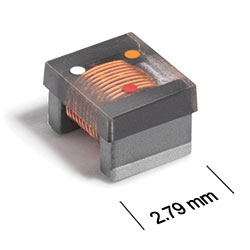
Physical characteristics
.gif "st413ramd-(1).gif")
Dimensions are in inches⁄mm
Terminal dimensions are without optional solder applied. For dimensions with optional solder, add 0.006 inches / 0,152 mm.
Visit Color Codes for RF Inductors for an explanation of the color dots.
General specification
Core Material:
Ferrite
Packaging:
2000 per 7″ reel Plastic tape: 8 mm wide, 0.3 mm thick, 4 mm pocket spacing, 2.0 mm pocket depth.
Temperature coefficient of inductance:
+100 to +350 ppm/°C.
Soldering/Washing
Moisture Sensitivity Level (MSL):
1 (unlimited floor life at <30°C / 85% relative humidity).
Resistance to soldering heat:
Max three 40 second reflows at +260°C, parts cooled to room temperature between cycles.
Refer to Soldering Coilcraft Components before soldering.