Datasheet
3D Model
Specifications
Electrical specifications at 25°C.
| Part number 1 |
Inductance (µH)
2
(Tolerance: ±5%) |
Impedance typ (Ω)
@ 10.0 MHz |
Q min
@ 2.5 MHz 3 |
SRF min (MHz) 4 | DCR max (Ω) 5 | Imax (mA) | Color code |
|---|---|---|---|---|---|---|---|
| ST336RAM223JRZ | 22 | 1620 | 13 | 15 | 6.70 | 75 | Green |
Notes
- When ordering, please specify termination and screening codes: e.g. ST336RAM223JRZ.
- Inductance measured at 0.1 Vrms, using Coilcraft SMD-A fixture in Agilent/HP 4286A impedance analyzer or equivalent with Coilcraft-provided correlation pieces.
- Q measured on Agilent/HP 4291A with Agilent/HP 16197A test fixture or equivalents.
- SRF measured using Agilent/HP 8753ES network analyzer or equivalent with Coilcraft SMD-D test fixture.
- DCR measured on a Keithley 580 Micro-ohmmeter or equivalent with a Coilcraft CCF858 test fixture.
Termination:
- R = Matte tin over nickel over silver-platinum-glass frit.
- Q= Tin-silver-copper (95.5/4/0.5) over tin over nickel over silver-platinum-glass frit. (Special order, added cost)
- P = Tin-lead (63/37) over tin over nickel over silverplatinum-glass frit. (Special order, added cost)
Screening:
- Z = Unscreened
- H = Coilcraft CP-SA-10001 Group A
- Screening performed to the document’s latest revision.
- Lot qualification (Group B) available.
- Custom testing also available.
- Country of origin restrictions available; prefix options G or F.
Environmental
Ambient temperature range:
–40°C to +85°C with Imax current.
Storage temperature range:
Component: –55°C to +100°C.
Packaging: –55°C to +80°C.
Packaging: –55°C to +80°C.
Maximum part temperature:
+100°C (ambient + temp rise).
Failures in Time (FIT) / Mean Time Between Failures (MTBF):
Performance curves
L vs Frequency

Q vs Frequency

Impedance vs Frequency

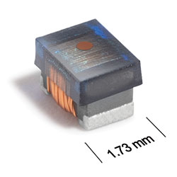
Physical characteristics

| A max | B max | C max | D ref | E | F | G | H | I | J | |
|---|---|---|---|---|---|---|---|---|---|---|
| 0.090 | 0.068 | 0.060 | 0.020 | 0.050 | 0.016 | 0.040 | 0.070 | 0.040 | 0.030 | inches |
| 2,29 | 1,73 | 1,52 | 0,51 | 1,27 | 0,41 | 1,02 | 1,78 | 1,02 | 0,76 | mm |
General specification
Core Material:
Ferrite
Weight:
16.7– 18.0 mg
Packaging:
2000/7″ reel; Plastic tape: 8 mm wide, 0.23 mm thick, 4 mm pocket spacing, 1.6 mm pocket depth.
Soldering/Washing
Moisture Sensitivity Level (MSL):
1 (unlimited floor life at <30°C / 85% relative humidity).
Resistance to soldering heat:
Max three 40 second reflows at +260°C, parts cooled to room temperature between cycles.
Refer to Soldering Coilcraft Components before soldering.