Datasheet
3D Model
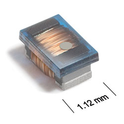
ST312RAM Series
Chip Inductors for Critical Applications
ST312RAM Series features ferrite construction for high current handling.
- Higher inductance values than ceramic 0603 inductors.
- Heavier gauge wire for low DCR.
- Inductance values from 15 nH to 10 μH.
- Matte tin over nickel over silver-platinum-glass frit terminations.
Specifications
Electrical specifications at 25°C.
| Part number 1 |
Inductance (nH)
2
(Tolerance: ±5%) |
Impedance typ (Ω)
@ 100 MHz |
Q min 3 | SRF min (MHz) 4 | DCR max (Ω) 5 | Imax (A) | Color code |
|---|---|---|---|---|---|---|---|
| ST312RAM15NJRZ | 15 @ 7.9 MHz | 10.0 | 10 @ 7.9 MHz | 2800 | 0.023 | 1.2 | Yellow |
| ST312RAM33NJRZ | 33 @ 7.9 MHz | 19.0 | 10 @ 7.9 MHz | 1840 | 0.028 | 1.2 | Red |
| ST312RAM39NJRZ | 39 @ 7.9 MHz | 23.0 | 13 @ 7.9 MHz | 2200 | 0.115 | 0.60 | Green |
| ST312RAM47NJRZ | 47 @ 7.9 MHz | 42.0 | 13 @ 7.9 MHz | 2250 | 0.052 | 1.1 | White |
| ST312RAM50NJRZ | 50 @ 7.9 MHz | 31.0 | 15 @ 7.9 MHz | 1830 | 0.052 | 1.1 | Violet |
| ST312RAM68NJRZ | 68 @ 7.9 MHz | 39.0 | 15 @ 7.9 MHz | 1500 | 0.150 | 0.50 | Gray |
| ST312RAM72NJRZ | 72 @ 7.9 MHz | 60.0 | 15 @ 7.9 MHz | 1800 | 0.065 | 1.0 | Blue |
| ST312RAM85NJRZ | 85 @ 7.9 MHz | 51.0 | 15 @ 7.9 MHz | 1600 | 0.065 | 1.0 | Brown |
| ST312RAM111JRZ | 110 @ 7.9 MHz | 70.0 | 12 @ 7.9 MHz | 980 | 0.060 | 1.1 | Red |
| ST312RAM121JRZ | 120 @ 7.9 MHz | 76.0 | 12 @ 7.9 MHz | 920 | 0.089 | 0.90 | Black |
| ST312RAM151JRZ | 150 @ 7.9 MHz | 89.0 | 15 @ 7.9 MHz | 1050 | 0.093 | 0.85 | Yellow |
| ST312RAM201JRZ | 200 @ 7.9 MHz | 120 | 15 @ 7.9 MHz | 880 | 0.115 | 0.80 | Green |
| ST312RAM241JRZ | 240 @ 7.9 MHz | 140 | 12 @ 7.9 MHz | 720 | 0.120 | 0.70 | Violet |
| ST312RAM271JRZ | 270 @ 7.9 MHz | 173 | 12 @ 7.9 MHz | 600 | 0.220 | 0.55 | Brown |
| ST312RAM361JRZ | 360 @ 7.9 MHz | 210 | 15 @ 7.9 MHz | 700 | 0.210 | 0.55 | Blue |
| ST312RAM391JRZ | 390 @ 7.9 MHz | 240 | 15 @ 7.9 MHz | 700 | 0.300 | 0.50 | Black |
| ST312RAM421JRZ | 420 @ 7.9 MHz | 250 | 11 @ 7.9 MHz | 685 | 0.330 | 0.50 | Red |
| ST312RAM471JRZ | 470 @ 7.9 MHz | 306 | 12 @ 7.9 MHz | 460 | 0.370 | 0.48 | Orange |
| ST312RAM561JRZ | 560 @ 7.9 MHz | 371 | 12 @ 7.9 MHz | 400 | 0.490 | 0.42 | Blue |
| ST312RAM601JRZ | 600 @ 7.9 MHz | 372 | 16 @ 7.9 MHz | 540 | 0.552 | 0.36 | Blue |
| ST312RAM681JRZ | 680 @ 7.9 MHz | 420 | 12 @ 7.9 MHz | 420 | 0.460 | 0.36 | Orange |
| ST312RAM821JRZ | 820 @ 7.9 MHz | 507 | 12 @ 7.9 MHz | 260 | 0.580 | 0.34 | Green |
| ST312RAM102JRZ | 1000 @ 7.9 MHz | 663 | 13 @ 7.9 MHz | 320 | 0.840 | 0.32 | Black |
| ST312RAM152JRZ | 1500 @ 7.9 MHz | 944 | 17 @ 7.9 MHz | 330 | 1.300 | 0.22 | Orange |
| ST312RAM222JRZ | 2200 @ 7.9 MHz | 5220 | 12 @ 2.5 MHz | 65 | 1.100 | 0.25 | Red |
| ST312RAM472JRZ | 4700 @ 7.9 MHz | 2100 | 12 @ 7.9 MHz | 45 | 1.500 | 0.22 | Yellow |
| ST312RAM103JRZ | 10000 @ 2.5 MHz | 1400 | 9 @ 2.5 MHz | 30 | 4.500 | 0.10 | Gray |
Notes
- When ordering, please specify termination and screening codes: e.g. ST312RAM103JRZ.
- Inductance measured using a Coilcraft SMD-A fixture in an Agilent/ HP 4286A impedance analyzer or equivalent with Coilcraft-provided correlation pieces.
- Q measured at the same frequency as inductance using an Agilent/ HP 4291A with an Agilent/HP 16197A test fixture or equivalents.
- SRF measured using an Agilent/HP 8753ES network analyzer or equivalent and a Coilcraft SMD-D test fixture.
- DCR measured on a Keithley 580 micro-ohmmeter or equivalent and a Coilcraft CCF1010 test fixture.
Termination:
- R = Matte tin over nickel over silver-platinum-glass frit.
- Q = Tin-silver-copper (95.5/4/0.5) over tin over nickel over silver-platinum-glass frit. (Special order, added cost)
- P = Tin-lead (63/37) over tin over nickel over silver-platinum-glass frit. (Special order, added cost)
Screening:
- Z = Unscreened
- H = Coilcraft CP-SA-10001 Group A
- Screening performed to the document’s latest revision.
- Lot qualification (Group B) available.
- Custom testing also available.
- Country of origin restrictions available; prefix option G.
Environmental
Ambient temperature range:
–40°C to +85°C with Irms current.
Storage temperature range:
Component: –55°C to +100°C.
Packaging: –55°C to +80°C.
Packaging: –55°C to +80°C.
Maximum part temperature:
+100°C (ambient + temp rise).
Failures in Time (FIT) / Mean Time Between Failures (MTBF):
Performance curves
L vs Frequency

Q vs Frequency

Z vs Frequency

Physical characteristics

| A max | B max | C max | D ref | E | F | G | H | I | J | |
|---|---|---|---|---|---|---|---|---|---|---|
| 0.071 | 0.044 | 0.036 | 0.015 | 0.030 | 0.013 | 0.034 | 0.040 | 0.025 | 0.025 | inches |
| 1,80 | 1,12 | 0,91 | 0,38 | 0,76 | 0,33 | 0,86 | 1,02 | 0,64 | 0,64 | mm |
General specification
Core Material:
Ferrite
Weight:
4.3 – 5.7 mg
Packaging:
2000 per 7′′ reel; Paper tape: 8 mm wide, 1.0 mm thick, 4 mm pocket spacing.
Temperature coefficient of inductance:
+50 to +300 ppm/°C.
Soldering/Washing
Moisture Sensitivity Level (MSL):
1 (unlimited floor life at <30°C / 85% relative humidity).
Resistance to soldering heat:
Max three 40 second reflows at +260°C, parts cooled to room temperature between cycles.
Refer to Soldering Coilcraft Components before soldering.