Specifications
| Part number 1 |
Inductance (nH)
2
(Tolerance: ±5%) |
SRF typ (MHz) 3 | DCR max (mΩ) 4 | Imax (mA) |
|---|---|---|---|---|
| ST235RAM560JAZ | 56 | 1900 | 105.000 | 600 |
Notes
- When ordering, please specify termination and screening codes: e.g. ST235RAM561JAZ.
- Inductance measured at 7.9 MHz using a Coilcraft SMD-F test fixture and Coilcraft-provided correlation pieces with an Agilent/HP 4286 impedance analyzer.
- SRF measured using Agilent/HP 8753D network analyzer and Coilcraft SMD -D test fixture.
- DCR measured on Cambridge Technology micro-ohmmeter and a Coilcraft CCF858 test fixture.
Termination:
- A = RoHS compliant gold over nickel over silver-palladium-glass frit.
- C = Tin-lead (63/37) over silver-platinum-glass frit. (Special order, added cost)
- F = Tin-silver-copper (95.5/4/0.5) over silver-platinum-glass frit. (Special order, added cost)
- R = RoHS compliant matte tin over nickel over silver-platinum-glass frit. (Special order, added cost)
- P = Tin-lead (63/37) over tin over nickel over silver-platinum-glass frit. (Special order, added cost)
- Q = Tin-silver-copper (95.5/4/0.5) over tin over nickel over silver-platinum-glass frit. (Special order, added cost)
Screening:
- Z = Unscreened
- H = Coilcraft CP-SA-10001 Group A
- Screening performed to the document’s latest revision.
- Lot qualification (Group B) available.
- Custom testing also available.
- Country of origin restrictions available; prefix option G.
Environmental
Ambient temperature range:
–40°C to +85°C with Imax current
Storage temperature range:
Component: –55°C to +100°C.
Packaging: –55°C to +80°C
Packaging: –55°C to +80°C
Maximum part temperature:
+100°C (ambient + temp rise)
Failures in Time (FIT) / Mean Time Between Failures (MTBF):
Performance curves
Typical L vs Frequency

Typical Q vs Frequency

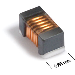
Physical characteristics

| A max | B max | C max | D | E | F | G | H | |
| 0.044 | 0.026 | 0.026 | 0.020 | 0.009 | 0.017 | 0.018 | 0.026 | inches |
| 1,12 | 0,66 | 0,66 | 0,51 | 0,23 | 0,43 | 0,46 | 0,66 | mm |
Note: Dimensions are before optional solder application. For maximum overall dimensions including solder, add 0.0025 in / 0,064 mm to B and 0.006 in / 0,15 mm to A and C.
General specification
Core Material:
Ferrite
Packaging:
2000 per 7″ reel. Paper tape: 8 mm wide, 0.68 mm thick, 2 mm pocket spacing.
Temperature coefficient of inductance:
+25 to +155 ppm/°C
Soldering/Washing
Moisture Sensitivity Level (MSL):
1 (unlimited floor life at <30°C / 85% relative humidity).
Resistance to soldering heat:
Max three 40 second reflows at +260°C, parts cooled to room temperature between cycles.
Refer to Soldering Coilcraft Components before soldering.