Datasheet
3D Model
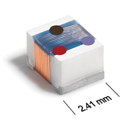
ST413RAE Series
Chip Inductors for Critical Applications
These chip inductors have been designed especially for high frequency applications. Their ceramic construction delivers the highest possible SRF and excellent Q values.
The non-magnetic coilform also ensures the utmost in thermal stability, predictability and batch consistency.
Specifications
Electrical specifications at 25°C.
| Part number 1 | Inductance (nH) 2 | Tolerance (%) | Q min 3 | SRF min (MHz) 4 | DCR max (Ω) 5 | Imax (mA) |
|---|---|---|---|---|---|---|
| ST413RAE100JRZ | 10 @ 50.0 MHz | 5 | 50 @ 500 MHz | 3000 | 0.08 | 1000 |
| ST413RAE120JRZ | 12 @ 50.0 MHz | 5 | 50 @ 500 MHz | 3000 | 0.09 | 1000 |
| ST413RAE150JRZ | 15 @ 50.0 MHz | 5 | 50 @ 500 MHz | 3000 | 0.14 | 1000 |
| ST413RAE180JRZ | 18 @ 50.0 MHz | 5 | 50 @ 350 MHz | 2500 | 0.11 | 1000 |
| ST413RAE220JRZ | 22 @ 50.0 MHz | 5,2,1 | 55 @ 350 MHz | 2000 | 0.12 | 1000 |
| ST413RAE270_RZ | 27 @ 50.0 MHz | 5,2,1 | 55 @ 350 MHz | 1500 | 0.13 | 1000 |
| ST413RAE330_RZ | 33 @ 50.0 MHz | 5,2,1 | 60 @ 350 MHz | 1500 | 0.14 | 1000 |
| ST413RAE390_RZ | 39 @ 50.0 MHz | 5,2,1 | 60 @ 350 MHz | 1500 | 0.15 | 1000 |
| ST413RAE470_RZ | 47 @ 50.0 MHz | 5,2,1 | 65 @ 350 MHz | 1350 | 0.16 | 1000 |
| ST413RAE560_RZ | 56 @ 50.0 MHz | 5,2,1 | 65 @ 350 MHz | 1150 | 0.18 | 1000 |
| ST413RAE680_RZ | 68 @ 50.0 MHz | 5,2,1 | 65 @ 350 MHz | 1050 | 0.20 | 1000 |
| ST413RAE820_RZ | 82 @ 50.0 MHz | 5,2,1 | 60 @ 350 MHz | 950 | 0.22 | 1000 |
| ST413RAE101_RZ | 100 @ 25.0 MHz | 5,2,1 | 60 @ 350 MHz | 950 | 0.56 | 650 |
| ST413RAE121_RZ | 120 @ 25.0 MHz | 5,2,1 | 60 @ 350 MHz | 900 | 0.63 | 650 |
| ST413RAE151_RZ | 150 @ 25.0 MHz | 5,2,1 | 45 @ 100 MHz | 850 | 0.70 | 580 |
| ST413RAE181_RZ | 180 @ 25.0 MHz | 5,2,1 | 45 @ 100 MHz | 700 | 0.77 | 620 |
| ST413RAE221_RZ | 220 @ 25.0 MHz | 5,2,1 | 45 @ 100 MHz | 600 | 0.84 | 500 |
| ST413RAE271_RZ | 270 @ 25.0 MHz | 5,2,1 | 45 @ 100 MHz | 550 | 0.91 | 500 |
| ST413RAE331_RZ | 330 @ 25.0 MHz | 5,2,1 | 45 @ 100 MHz | 500 | 1.05 | 450 |
| ST413RAE391_RZ | 390 @ 25.0 MHz | 5,2,1 | 45 @ 100 MHz | 465 | 1.12 | 470 |
| ST413RAE471_RZ | 470 @ 25.0 MHz | 5,2,1 | 45 @ 100 MHz | 425 | 1.19 | 470 |
| ST413RAE561_RZ | 560 @ 25.0 MHz | 5,2,1 | 45 @ 100 MHz | 415 | 1.33 | 400 |
| ST413RAE621_RZ | 620 @ 25.0 MHz | 5,2,1 | 45 @ 100 MHz | 375 | 1.40 | 300 |
| ST413RAE681_RZ | 680 @ 25.0 MHz | 5,2,1 | 45 @ 100 MHz | 340 | 1.47 | 400 |
| ST413RAE751_RZ | 750 @ 25.0 MHz | 5,2,1 | 45 @ 100 MHz | 330 | 1.54 | 360 |
| ST413RAE821_RZ | 820 @ 25.0 MHz | 5,2,1 | 45 @ 100 MHz | 325 | 1.61 | 400 |
| ST413RAE911_RZ | 910 @ 25.0 MHz | 5,2,1 | 35 @ 50.0 MHz | 305 | 1.68 | 380 |
| ST413RAE102_RZ | 1000 @ 25.0 MHz | 5,2,1 | 35 @ 50.0 MHz | 290 | 1.75 | 370 |
Notes
- When ordering, specify tolerance, termination and screening codes: e.g. ST413RAE102JRZ.
- Inductance measured using a Coilcraft SMD-A fixture in an Agilent/HP 4286A impedance analyzer with Coilcraft-provided correlation pieces.
- Q measured using an Agilent/HP 4291A with an Agilent/HP 16193 test fixture.
- SRF measured using an Agilent/HP 8753D network analyzer and a Coilcraft SMD-D test fixture.
- . DCR measured on a Cambridge Technology micro-ohmmeter and a Coilcraft CCF840 test fixture.
Tolerance:
- F = 1%
- G = 2%
- J = 5%
Termination:
- R = Matte tin over nickel over silver-platinum glass frit.
- P = Tin-lead (63/37) over tin over nickel over silver-platinum-glass frit. (Special order, added cost)
- Q = Tin-silver-copper (95.5/4/0.5) over tin over nickel over silver-platinum-glass frit. (Special order, added cost)
- L = Silver-palladium-platinum glass frit. (Special order, added cost)
- S = Tin-lead (63/37) over silver-platinum-glass frit. (Special order, added cost)
- T = Tin-silver-copper (95.5/4/0.5) over silver-platinumglass frit. (Special order, added cost)
Screening:
- Z = Unscreened
- Y = Unscreened (SLDC Option A)
- W = Unscreened (SLDC Option B)
- H = Coilcraft CP-SA-10001 Group A
- G = Coilcraft CP-SA-10001 Group A (SLDC Option A)
- D = Coilcraft CP-SA-10001 Group A (SLDC Option B)
- Screening performed to the document’s latest revision.
- Lot qualification (Group B) available.
- Custom testing also available.
Environmental
Ambient temperature range:
–40°C to +125°C with Imax current
Storage temperature range:
Component: –55°C to +140°C
Tape and reel packaging: –55°C to +80°C
Tape and reel packaging: –55°C to +80°C
Maximum part temperature:
+140°C (ambient + temp rise)
Failures in Time (FIT) / Mean Time Between Failures (MTBF):
Performance curves
L vs Frequency

Q vs Frequency


General specification
Core Material:
Ceramic
Packaging:
2000 per 7″ reel Plastic tape: 8 mm wide, 0.23 mm thick, 4 mm pocket spacing, 1.8 mm pocket depth.
Temperature coefficient of inductance:
+25 to +155 ppm/°C
Soldering/Washing
Moisture Sensitivity Level (MSL):
1 (unlimited floor life at <30°C / 85% relative humidity)
Resistance to soldering heat:
Max three 40 second reflows at +260°C, parts cooled to room temperature between cycles.
Refer to Soldering Coilcraft Components before soldering.