Datasheet
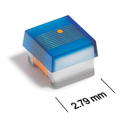
3D Model
Specifications
Electrical specifications at 25°C.
| Part number 1 | Inductance (nH) 2 | Tolerance (%) |
Q min
@ 100 MHz 3 |
SRF min (MHz) 4 | DCR max (mΩ) 5 | Imax (mA) | Color code 6 |
|---|---|---|---|---|---|---|---|
| ML413RAA101_LZ | 100 | 5,2,1 | 37 | 900 | 560.00 | 440 | Violet |
Notes
- When ordering, please specify tolerance code: e.g. ML413RAA102GLZ.
- Inductance measured using a Coilcraft SMD-A fixture in an Agilent/HP 4286A impedance analyzer or equivalent with Coilcraft-provided correlation pieces.
- Q measured using an Agilent/HP 4291A with an AgilentHP 16197A test fixture or equivalents.
- SRF measured using an Aglilent/HP 8753ES network analyzer or equivalent and a Coilcraft CCF1297 test fixture.
- DCR measured on a Keithley 580 micro-ohmmeter or equivalent and a Coilcraft CCF858 test fixture.
- Current production parts are marked with one dot. Prior production parts were marked with three dots. Part marking does not indicate polarity.
Tolerance:
- F = 1%
- G = 2%
- J = 5%
Environmental
Ambient temperature range:
–55°C to +125°C with Imax current
Storage temperature range:
Component: –55°C to +155°C
Tape and reel packaging: –55°C to +80°C
Tape and reel packaging: –55°C to +80°C
Maximum part temperature:
+155°C (ambient + temp rise)
Failures in Time (FIT) / Mean Time Between Failures (MTBF):
Performance curves
L vs Frequency

Q vs Frequency


General specification
Core Material:
Ceramic
Packaging:
2000 per 7″ reel Plastic tape: 8 mm wide, 0.3 mm thick, 4 mm pocket spacing, 2.0 mm pocket depth.
Temperature coefficient of inductance:
+25 to +155 ppm/°C
Soldering/Washing
Moisture Sensitivity Level (MSL):
1 (unlimited floor life at <30°C / 85% relative humidity)
Resistance to soldering heat:
Max three 40 second reflows at +260°C, parts cooled to room temperature between cycles.
Refer to Soldering Coilcraft Components before soldering.