Datasheet
3D Model
Specifications
Electrical specifications at 25°C.
| Part number 1 | Inductance (nH) 2 | Tolerance (%) |
Q min
@ 100 MHz 3 |
SRF min (MHz) 4 | DCR max (Ω) 5 | Imax (mA) |
|---|---|---|---|---|---|---|
| AR413RAFR22_PZ | 220 | 5,2,1 | 34 | 600 | 1.2 | 250 |
Notes
- When ordering, please specify tolerance, termination and screening codes: e.g. AR413RAFR56JPZ
- Inductance measured using a Coilcraft SMD-A fixture in an Agilent/ HP 4286A impedance analyzer with Coilcraft-provided correlation pieces.
- Q measured using an Agilent/HP 4291A with an Agilent/HP 16193 test fixture.
- SRF measured using an Agilent/HP 8720D network analyzer and a Coilcraft SMD-D test fixture.
- DCR measured on a Cambridge Technology micro-ohmmeter and a Coilcraft CCF840 test fixture. For other operating temperatures, use this DCR at Temperature calculator.
- Current that causes a 15°C temperature rise from 25°C ambient. This information is for reference only and does not represent absolute maximum ratings.
Tolerance:
F = 1% G = 2% J = 5%Termination:
P = Tin-lead (63/37) over tin over nickel over silverplatinum-glass frit.Screening:
- Z = Unscreened
- H = Coilcraft CP-SA-10001 Group A
- 1 = EEE-INST-002 (Family 3) Level 1
- 2 = EEE-INST-002 (Family 3) Level 2
- 3 = EEE-INST-002 (Family 3) Level 3
- 4 = MIL-STD-981 (Family 50) Class B
- 5 = MIL-STD-981 (Family 50) Class S
- F = ESCC3201 (F4 operational life performed at 90°C)
- Screening performed to the document’s latest revision.
- Lot qualification (Group B) available.
- Custom testing also available.
- Country of origin restrictions available; prefix option G.
Environmental
Ambient temperature range:
–55°C to +125°C with Imax current.
Storage temperature range:
Component: –55°C to +140°C.
Tape and reel packaging: –55°C to +80°C
Tape and reel packaging: –55°C to +80°C
Maximum part temperature:
+140°C (ambient + temp rise)
Failures in Time (FIT) / Mean Time Between Failures (MTBF):
Performance curves
L vs Frequency

Q vs Frequency

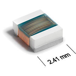
Physical characteristics

| A max | B max | C max | E | F | G | H | I | J | |
|---|---|---|---|---|---|---|---|---|---|
| 0.105 | 0.095 | 0.045 | 0.080 | 0.020 | 0.060 | 0.100 | 0.040 | 0.050 | inches |
| 2,67 | 2,41 | 1,14 | 2,03 | 0,51 | 1,52 | 2,54 | 1,02 | 1,27 | mm |
Dimensions are before optional solder application.
For maximum overall dimensions including solder, add 0.006 in / 0,152 mm to A and C.
General specification
Core Material:
Ceramic
Weight:
16 – 19 g
Temperature coefficient of inductance:
+25 to +125 ppm/°C
Soldering/Washing
Moisture Sensitivity Level (MSL):
1 (unlimited floor life at <30°C / 85% relative humidity)
Resistance to soldering heat:
Max three 40 second reflows at +260°C, parts cooled to room temperature between cycles
Refer to Soldering Coilcraft Components before soldering.
PCB Washing:
Tested to MIL-STD-202 Method 215 plus an additional aqueous wash. More info