Datasheet
3D Model
Specifications
Electrical specifications at 25°C.
| Part number 1 | Inductance (nH) 2 | Tolerance (%) 3 | 900 MHz |
Q min
@ 150 MHz 4 |
SRF min (MHz) 5 | DCR max (mΩ) 6 | Imax (mA) 7 |
|---|---|---|---|---|---|---|---|
| Q typ 4 | |||||||
| CP312RAQR10_RZ | 100 | 5,3,2 | 62 | 28 | 1100.00 | 707.000 | 290 |
Notes
- When ordering, please specify tolerance, termination and screening codes: e.g. CP312RAQR47JRZ.
- Inductance measured using a Coilcraft SMD-A fixture in an Agilent/ HP E4982A impedance analyzer with Coilcraft-provided correlation pieces.
- Tolerances in bold are stocked for immediate shipment.
- Q measured using an Agilent/HP4991A with an Agilent/HP16197 test fixture.
- SRF measured using an Agilent/HP 5071C/8722ES network analyzer and a Coilcraft CCF1052 test fixture.
- DCR measured on a micro-ohmmeter and a Coilcraft CCF1010/A test fixture.
- Maximum current that can be applied at 125°C.
Tolerance:
- G = 2%
- H = 3%
- J = 5%
Termination:
- R = Matte tin over nickel over silver-platinum glass frit
- P = Tin-lead (63/37) over tin over nickel over silver platinum-glass frit
- Q = Tin-silver-copper (95.5/4/0.5) over tin over nickel over silver-platinum-glass frit
Screening:
- Z = Unscreened
- H = Coilcraft CP-SA-10001 Group A
- Screening performed to the document’s latest revision.
- Custom testing also available.
- Country of origin restrictions available; prefix option G.
Environmental
Ambient temperature range:
–40°C to +125°C with Irms current.
Storage temperature range:
Component: –55°C to +140°C.
Tape and reel packaging: –55°C to +80°C.
Tape and reel packaging: –55°C to +80°C.
Maximum part temperature:
+140°C (ambient + temp rise).
Failures in Time (FIT) / Mean Time Between Failures (MTBF):
Performance curves
Typical L vs Frequency

Typical Q vs Frequency

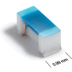
Physical characteristics

| A max | B max | C max | D | E | F | G | H | |
| 0.067 | 0.039 | 0.035 | 0.028 | 0.013 | 0.033 | 0.016 | 0.051 | inches |
| 1,70 | 0,99 | 0,89 | 0,71 | 0,33 | 0,85 | 0,40 | 1,29 | mm |
Notes: Dimensions are before optional solder application. For maximum overall dimensions including solder, add 0.0025 in / 0,064 mm to B and 0.006 in / 0,15 mm to A and C.
General specification
Core Material:
Ceramic
Weight:
3 – 4 mg
Packaging:
2000 per 7” reel; Paper tape: 8 mm wide, 0.95 mm thick, 4 mm pocket spacing.
Temperature coefficient of inductance:
+25 to +125 ppm/°C
Soldering/Washing
Moisture Sensitivity Level (MSL):
1 (unlimited floor life at <30°C / 85% relative humidity).
Resistance to soldering heat:
Max three 40 second reflows at +260°C, parts cooled to room temperature between cycles.
Refer to Soldering Coilcraft Components before soldering.
PCB Washing:
Tested to MIL-STD-202 Method 215 plus an additional aqueous wash. See Doc787_PCB_Washing.pdf.