3D Model
Datasheet
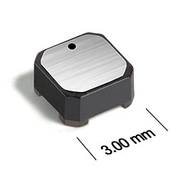
AE412PJD Series
Common Mode Chokes for Critical Applications
- Only 1.4 mm high and 3 mm square
- Ideal for use in both power line and signal line applications
- Common- and differential-mode filtering in a single device
- Up to 540 MHz differential mode cutoff frequency
- Can be used as coupled inductors for SEPIC applications
Specifications
| Part number 1 |
Common mode peak impedance (kΩ) |
Cutoff frequency (MHz) 2 |
Inductance (µH) 3 | Irms (A) 4 | DCR max (Ω) 5 |
Isolation Voltage (Vrms) 6 |
|---|---|---|---|---|---|---|
| AE412PJD391NPZ | 1.03 @ 330 MHz | 540 | 0.39 ±30% | 1.45 | 0.071 | 100 |
| AE412PJD561MPZ | 1.44 @ 240 MHz | 540 | 0.56 ±20% | 1.37 | 0.079 | 100 |
| AE412PJD102MPZ | 2.43 @ 160 MHz | 330 | 1.0 ±20% | 1.08 | 0.129 | 100 |
| AE412PJD152MPZ | 3.56 @ 130 MHz | 330 | 1.5 ±20% | 0.86 | 0.204 | 100 |
| AE412PJD182MPZ | 4.37 @ 110 MHz | 280 | 1.8 ±20% | 0.78 | 0.273 | 100 |
| AE412PJD222MPZ | 4.67 @ 100 MHz | 330 | 2.2 ±20% | 0.75 | 0.3 | 100 |
| AE412PJD332MPZ | 7.28 @ 81 MHz | 220 | 3.3 ±20% | 0.67 | 0.337 | 100 |
| AE412PJD472MPZ | 10.7 @ 66 MHz | 210 | 4.7 ±20% | 0.54 | 0.503 | 100 |
| AE412PJD682MPZ | 12.1 @ 54 MHz | 290 | 6.8 ±20% | 0.49 | 0.622 | 100 |
| AE412PJD103MPZ | 17.8 @ 47 MHz | 330 | 10 ±20% | 0.38 | 1.04 | 100 |
| AE412PJD153MPZ | 22.6 @ 33 MHz | 140 | 15 ±20% | 0.32 | 1.42 | 100 |
| AE412PJD183MPZ | 29.0 @ 31 MHz | 94.0 | 18 ±20% | 0.31 | 1.55 | 100 |
| AE412PJD223MPZ | 27.3 @ 24 MHz | 88.0 | 22 ±20% | 0.28 | 1.89 | 100 |
| AE412PJD333MPZ | 41.1 @ 21 MHz | 59.0 | 33 ±20% | 0.23 | 2.84 | 100 |
| AE412PJD473MPZ | 48.7 @ 18 MHz | 50.0 | 47 ±20% | 0.19 | 4.03 | 100 |
| AE412PJD683MPZ | 64.5 @ 14 MHz | 48.0 | 68 ±20% | 0.16 | 6.11 | 100 |
| AE412PJD104MPZ | 94.7 @ 13 MHz | 47.0 | 100 ±20% | 0.13 | 8.54 | 100 |
| AE412PJD124MPZ | 116 @ 11 MHz | 37.0 | 120 ±20% | 0.13 | 9.23 | 100 |
| AE412PJD154MPZ | 135 @ 9 MHz | 27.0 | 150 ±20% | 0.11 | 12.4 | 100 |
| AE412PJD184MPZ | 170 @ 8 MHz | 39.0 | 180 ±20% | 0.10 | 15.32 | 100 |
| AE412PJD224MPZ | 155 @ 7 MHz | 27.0 | 220 ±20% | 0.09 | 18.56 | 100 |
| AE412PJD334MPZ | 222 @ 6 MHz | 16.0 | 330 ±20% | 0.07 | 27.7 | 100 |
Notes
- When ordering, please specify termination and screening codes: e.g. ML412PJD334MPZ.
- Frequency at which the differential mode attenuation equals −3 dB.
- Inductance shown for each winding, measured at 100 kHz, 0.1 Vrms, 0 Adc on an Agilent/HP 4284A LCR meter or equivalent.
- Current that causes a 40°C temperature rise from 25°C ambient. This information is for reference only and does not represent absolute maximum ratings.
- DCR is for each winding.
- Interwinding isolation (hipot) tested for one minute.
Termination:
- P = Tin-lead (63/37) over tin over nickel over silver-palladium-glass frit.
- R = Tin over nickel over silver-palladium-glass frit. Not suitable for applications or screening with pure tin restrictions.
- Q = Tin-silver-copper (95.5/4/0.5) over tin over nickel over silver-platinum-glass frit.
Testing:
- Z = Unscreened
- Y = Unscreened (SLDC Option A)
- W = Unscreened (SLDC Option B)
- H = Coilcraft CP-SA-10001 Group A
- G = Coilcraft CP-SA-10001 Group A (SLDC Option A)
- D = Coilcraft CP-SA-10001 Group A (SLDC Option B)
- 1 = EEE-INST-002 (Family 1) Level 1
- 2 = EEE-INST-002 (Family 1) Level 2
- 3 = EEE-INST-002 (Family 1) Level 3
- 4 = MIL-STD-981 (Family 04) Class B
- 5 = MIL-STD-981 (Family 04) Class S
- F = ESCC3201 (F4 operational life performed at 105°C)
- Screening performed to the document’s latest revision.
- Lot qualification (Group B) available.
- Testing T and U have been replaced with more detailed codes 4, 5, and 1, 2, 3, respectively. Codes T and U can still be used, if necessary. Custom testing also available.
- Country of origin restrictions available; prefix options G or F.
Environmental
Ambient temperature range:
–55°C to +105°C with Irms current.
Storage temperature range:
Component: –55°C to +155°C.
Tape and reel packaging: –55°C to +80°C.
Tape and reel packaging: –55°C to +80°C.
Maximum part temperature:
+155°C (ambient + temp rise).
Failures in Time (FIT) / Mean Time Between Failures (MTBF):
Performance curves
Attenuation (Ref: 50 Ohms)
")
Impedance vs Frequency


General specification
Core Material:
Ferrite
Weight:
48 – 66 mg
Winding to Winding Isolation:
100
Soldering/Washing
Moisture Sensitivity Level (MSL):
1 (unlimited floor life at <30°C / 85% relative humidity).
Resistance to soldering heat:
Max three 40 second reflows at +260°C, parts cooled to room temperature between cycles.
Refer to Soldering Coilcraft Components before soldering.
PCB Washing:
Tested to MIL-STD-202 Method 215 plus an additional aqueous wash. See Doc787_PCB_Washing.pdf.