Frequently Asked Questions
Cleaning / Washing
Core and winding losses
A detailed discussion of core and winding losses is provided in Choosing Inductors for Energy Efficient Power Applications.
Date code / Lot code
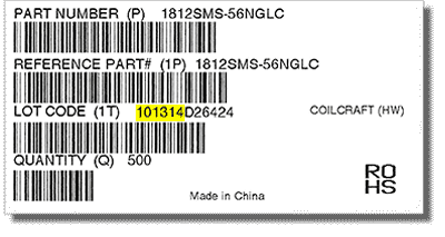
Coilcraft reel labels contain a manufacturing date code embedded in the first six characters of the "LOT CODE" field.
The date is in MMDDYY format. In the example below, the code 101314 = October 13, 2014.

Dash numbers
Therefore, 103 would be 10 × 10^3 (or 10 followed by three zeroes), equals 10,000 nH, equivalent to 10 µH.
Other examples:
- -394 = 39 × 10^4 = 390000 = 390,000 nH = 390 µH
- -102 = 10 × 10^2 = 1000 = 1000 nH = 1.0 µH
- -501 = 50 × 10^1 = 500 = 500 nH = 0.5 µH
Discontinued / Obsolescence / EOL / PCN / PDN
While Coilcraft has discontinued a small number of series, we will, when feasible, continue to support existing customers (with previous order history for this series). For many of these parts we have developed a newer series that surpasses the performance of the discontinued part. If you search for the discontinued part on our web site, you will be guided to the replacement part.
Coilcraft can notify your company in the event that products that you purchase are changed (Product Change Notice) or discontinued (Product Discontinuation Notice). Sign up for PCN and PDN emails here.
ESD (Electrostatic discharge)
Export Classification Number (ECCN)
Effects of Ground Plane
The effects of ground plane proximity depend on inductor geometry and test frequency, along with substrate thickness and dielectric constant. In many cases the effect is fairly small, but it can be significant in very tight-tolerance applications. The interaction of the magnetic field of an inductor with a metal ground plane is a complicated 3D E/M problem that requires careful measurement or simulation under specific application conditions. For this reason Coilcraft cannot quantify these effects in general.
Inductance of transformer secondaries
Junction temperature
Moisture Sensitivity Level (MSL)
Noise
Non-magnetic products
All of our air-core inductors are non-magnetic: Air-Core Inductors
All of our ceramic-core RF chip inductors are non-magnetic, with the exception of those with nickel in terminations. Ceramic Chip Inductors
Please contact us for any specific inquiry.
Polarity
Potting / Conformal coating / Encapsulating
Power ratings
There is a reason that we do not specify power ratings for our inductors. The more meaningful rating for inductors is the rms current rating. Inductor rms current ratings are derived by applying dc or low frequency ac current and measuring the resultant temperature rise. This allows for an accurate determination of temperature rise vs rms current, which can easily be related to temperature rise vs power loss by Power Loss = Irms2 × DCR.
In practice inductor losses can include high frequency core loss, skin effect and proximity effect, which can add to the temperature rise. While these losses are application dependent and should be verified in situ, Coilcraft offers tools for predicting frequency effects. Core loss, conductor loss, and temperature rise can be estimated using the Core & Winding Loss Calculator.
ESR vs frequency for chip inductors can be graphed using the RF Inductor Comparison Tool.
Ratings (Inductance, Q, DCR, SRF, Current, Voltage, Temperature)
Returns
Coilcraft standard products can be returned within thirty (30) days of receipt of product by contacting Customer Service Department for a Return Material Authorization (RMA). Returned merchandise must be in original packaging and conform to minimum package requirements. Returned merchandise may be subject to a restocking fee.
Safety agency approvals
Upon customer request, Coilcraft may obtain specific transformer listings, for example, per UL / IEC 60950 Harmonized Standard for “Safety of Information Technology Equipment.” However, doing so will not automatically qualify the end equipment for agency approval. The manufacturer still has to submit the entire product to UL for approval. Alternatively, Coilcraft can supply certain pertinent information about Hi Pot voltages and insulation to support customers with the approval process on a per request basis.
Some Coilcraft parts are designed to meet specific UL / CSA / IEC or other standards as noted on the particular Coilcraft data sheet.
For more information or further assistance, please contact technical support.
Selecting the best part
Yes, we provide many web based tools and applications notes that can help you select the correct part.
RF inductor finder Find every RF inductor that meets your specific requirements.
Power inductor finder Get a sortable list of products that fit your application.
Parametric Search See all available Coilcraft inductors - filter, sort and compare.
Additional Resources are also available on coilcraft.com - use the links below:
Converter inductor selector Input your parameters and get detailed inductor specifications.
Flyback transformer selector A structured listing of Coilcraft off-the-shelf flyback transformers.
We also provide cross references to IC applications and competitor parts:
IC / Inductor matching tool Get a list of Coilcraft parts suitable for 1000s of IC reference designs
Our Application Notes page contains valuable information for selecting the right component for many applications.
Common Mode Filter Design Guide, Common Mode Filter Inductor Analysis and Data Line Filtering.
Shelf life
For uncontrolled or unknown environments, our parts are good for one year in packing.
For uncontrolled or unknown environments, our shelf or floor life cannot be certified out of packaging.