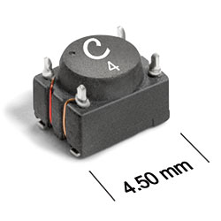
Datasheet
3D Model
Specifications
| Part number 1 | Lines |
Common mode peak impedance (kΩ) |
Cutoff frequency (kHz) |
Inductance min (mH) 2 |
Leakage Inductance max (nH) |
Irms (mA) 3 | DCR max (Ω) 4 |
Isolation Voltage (Vrms) |
|---|---|---|---|---|---|---|---|---|
| ST448RFT513BLZ | 2 | 2.01 @ 61.0 MHz | 670 | 0.036 | 100.000 | 370 | 0.320 | 250 |
Notes
- When ordering, please specify testing code: e.g. ST448RFT474BLZ.
- Inductance is for each winding, measured at test frequency using a Voltech AT3600 or equivalent.
- Current that causes a 20°C temperature rise from 25°C ambient.
- DCR is specified per winding.
Termination:
- L= RoHS compliant matte tin over nickel over phos-bronze
Testing:
- Z = Unscreened
- H = Group A screening per Coilcraft CP-SA-10001
Custom screening also available.
Environmental
Ambient temperature range:
–40°C to +85°C with Irms current.
Storage temperature range:
Component: –55°C to +105°C.
Tape and reel packaging: –40°C to +80°C.
Tape and reel packaging: –40°C to +80°C.
Maximum part temperature:
+105°C (ambient + temp rise).
Failures in Time (FIT) / Mean Time Between Failures (MTBF):
Performance curves
Attenuation vs Frequency - Differential Mode

Attenuation vs Frequency - Common Mode

Impedance vs Frequency - Differential Mode

Impedance vs Frequency - Common Mode


General specification
Core Material:
Ferrite
Weight:
78 – 86 mg
Packaging:
600/7″ reel Plastic tape: 12 mm wide, 0.4 mm thick, 8 mm pocket spacing, 3.43 mm pocket depth.
Soldering/Washing
Moisture Sensitivity Level (MSL):
1 (unlimited floor life at <30°C / 85% relative humidity.
Resistance to soldering heat:
Max three 40 second reflows at +260°C, parts cooled to room temperature between cycles.
Refer to Soldering Coilcraft Components before soldering.