3D Model
Datasheet
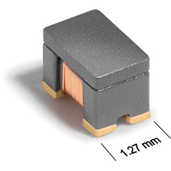
AR336FRA Series
Common Mode Chokes for Critical Applications
AR336FRA Series designed for high-speed USB 3.0, HDMI, SATA, IEEE1394 and LVDS applications.
- For common mode noise suppression in high speed differential signal lines: USB2.0, IEEE1394, LVDS, etc.
- Up to 3.4 GHz differential mode 3 dB cutoff frequency
- Up to 2 kOhms common mode peak impedance
- Up to 35 dB common mode noise attenuation.
- Passes NASA low outgassing specifications
Specifications
| Part number 1 | Lines |
Common mode peak impedance (kΩ) |
Cutoff frequency (GHz) 2 |
Common mode attenuation typ (dB) |
Inductance min (nH) 3 |
Irms (mA) | DCR max (Ω) 4 |
Isolation Voltage (Vrms) 5 |
||
|---|---|---|---|---|---|---|---|---|---|---|
| 10 MHz | 100 MHz | 500 MHz | ||||||||
| AR336FRA421MPZ | 2 | 0.22 @ 3.0 GHz | 3.5 | 0.9 | 4.5 | 7.1 | 23 | 500 | 0.12 | 250 |
| AR336FRA901MPZ | 2 | 0.29 @ 3.0 GHz | 2.5 | 0.5 | 7.3 | 12.4 | 47 | 500 | 0.17 | 250 |
| AR336FRA172MPZ | 2 | 0.64 @ 1.8 GHz | 1.8 | 4.4 | 12.3 | 16.9 | 84 | 500 | 0.25 | 250 |
| AR336FRA262MPZ | 2 | 0.82 @ 1.8 GHz | 1.5 | 7.6 | 15.3 | 20.1 | 147 | 500 | 0.26 | 250 |
| AR336FRA372MPZ | 2 | 1.06 @ 1.4 GHz | 0.82 | 9.7 | 18.5 | 23.4 | 189 | 500 | 0.32 | 250 |
| AR336FRA502MPZ | 2 | 1.42 @ 1.1 GHz | 0.70 | 8.2 | 20.3 | 26.1 | 273 | 500 | 0.37 | 250 |
| AR336FRA672MPZ | 2 | 1.75 @ 0.93 GHz | 0.46 | 12.5 | 22.9 | 28.2 | 322 | 500 | 0.45 | 250 |
| AR336FRA902MPZ | 2 | 2.06 @ 0.81 GHz | 0.47 | 10.7 | 24.8 | 29.8 | 413 | 250 | 0.65 | 250 |
Notes
- When ordering, please specify termination and testing codes: e.g. AR336FRA902MPZ.
- Frequency at which the differential mode attenuation equals −3 dB.
- Inductance measured at 100 MHz using an Agilent/HP 4286A impedance analyzer and a Coilcraft SMD-A fixture.
- DCR is specified per winding.
- Winding to winding isolation (hipot) tested for one minute.
Termination:
- P = Tin-lead (63/37) over tin over nickel over silver-palladium-glass frit.
- C = Tin-lead (63/37) over gold over nickel over silver-palladium-glass frit
- A = Gold over nickel over silver-palladium-glass frit
- R = Tin over nickel over silver-palladium-glass frit. Not suitable for applications or screening with pure tin restrictions.
Testing:
- Z = Unscreened
- H = Coilcraft CP-SA-10001 Group A
- G = Coilcraft CP-SA-10001 Group A (SLDC Option A)
- D = Coilcraft CP-SA-10001 Group A (SLDC Option B)
- F = ESCC3201 (F4 operational life performed at 90°C)
- 1 = EEE-INST-002 (Family 1) Level 1
- 2 = EEE-INST-002 (Family 1) Level 2
- 3 = EEE-INST-002 (Family 1) Level 3
- 4 = MIL-STD-981 (Family 11) Class B
- 5 = MIL-STD-981 (Family 11) Class S
- Screening performed to the document’s latest revision.
- Lot qualification (Group B) available.
Environmental
Ambient temperature range:
–40°C to +105°C with Irms current.
Storage temperature range:
Component: –55°C to +125°C.
Tape and reel packaging: –40°C to +80°C.
Tape and reel packaging: –40°C to +80°C.
Maximum part temperature:
+125°C (ambient + temp rise).
Failures in Time (FIT) / Mean Time Between Failures (MTBF):
Performance curves
Typical Attenuation

Typical Impedance vs Frequency

Schematics


General specification
Core Material:
Ferrite
Weight:
13.8 – 15.8 mg
Packaging:
2000 per 7″reel; 7500/13″ reel; Plastic tape: 8 mm wide, 0.23 mm thick, 4 mm pocket spacing, 1.5 mm pocket depth.
Soldering/Washing
Moisture Sensitivity Level (MSL):
1 (unlimited floor life at <30°C / 85% relative humidity).
Resistance to soldering heat:
Max three 40 second reflows at +260°C, parts cooled to room temperature between cycles.
Refer to Soldering Coilcraft Components before soldering.